Automatic laying device for waterproof membrane for outdoor building

An automatic laying and waterproof membrane technology, which is applied in the direction of buildings, building components, building structures, etc., can solve the problems of low levelness of manual laying, flat waterproof membrane, not worth promoting, etc., to achieve ingenious structural design and reduce manpower The effect of simple use and structure

Active Publication Date: 2019-11-08
泉州台商投资区笙沓新材料有限公司
6 Cites 1 Cited by

AI-Extracted Technical Summary

Problems solved by technology

[0003] At present, most of the laying of waterproof membranes is manually laid. The waterproof membranes are generally rolled in a cylindrical shape when they leave the factory. When laying, they need to be rolled up manua...

Method used

The beneficial effect of the present invention is: the present invention is simple in structure, and is easy to operate, and waterproof membrane can be pressed down by rotating cylinder and can be pushed to lay when body moves, and wat...

Abstract

The invention discloses an automatic laying device for a waterproof membrane for an outdoor building. The automatic laying device for the waterproof membrane for the outdoor building comprises a laying machine body, wherein a lifting slide groove is formed in the end surface of the bottom of the laying machine body in the form of left-right symmetry; a lifting slide frame is slidably installed inthe lifting slide groove; a telescopic slide cavity is formed in the end surface of the bottom of the lifting slide frame in the form of left-right symmetry; a telescopic slide block is slidably installed in the telescopic slide cavity; and a press plate flatly pressing the waterproof membrane is arranged at the bottoms of the end surfaces of the left side and the right side of the telescopic slide block separately. The automatic laying device for the waterproof membrane for the outdoor building is simple in structure, and convenient to operate; the waterproof membrane is jacked-pressed through a rotary barrel, so that the waterproof membrane is enabled to keep stable contact with the ground when the laying machine body is pushed to move; and through the reciprocating jacking-pressing of the press plate, the waterproof membrane can be flatly laid, the occurrence of a hollow phenomenon is prevented, and manpower use can be effectively reduced.

Application Domain

Roof toolsBuilding insulations

Technology Topic

Mechanical engineeringLeft–right symmetry

Image

  • Automatic laying device for waterproof membrane for outdoor building
  • Automatic laying device for waterproof membrane for outdoor building
  • Automatic laying device for waterproof membrane for outdoor building

Examples

  • Experimental program(1)

Example Embodiment

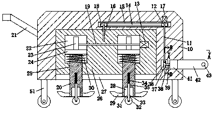
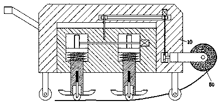
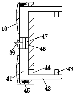
[0019] Combine below Figure 1-5 The present invention is described in detail, for the convenience of description, the orientations mentioned below are now specified as follows: figure 1 The projection relationship of itself is the same as the up, down, left, right, front, and rear directions.
[0020] refer to Figure 1-5 , according to an embodiment of the present invention, an automatic laying device for waterproof membranes for outdoor buildings includes a laying body 10, and a lifting chute 27 is symmetrically arranged in the end face of the bottom of the laying body 10, and the lifting chute 27 is slidably installed There is a lift carriage 26, a telescopic sliding cavity 25 is symmetrically arranged in the end face of the bottom of the lifting carriage 26, a telescopic sliding block 20 is slidably installed in the telescopic sliding cavity 25, and the bottom of the left and right end faces of the telescopic sliding block 20 is slidably installed. There is a pressure plate 29 for pressing the waterproof membrane 50 flat, a receiving groove 28 is formed in the bottom end face of the telescopic slider 20, and a sliding groove 35 is provided on the top wall of the receiving groove 28, and a sliding groove 35 is slidably installed in the The sliding plate 33, a first pressing spring 34 is connected between the top surface of the sliding plate 33 and the top wall of the chute 35, the sliding plate 33 protrudes out of the bottom end surface of the accommodating groove 28, and the bottom end is rotatably installed with a The rotating drum 32 that the waterproof membrane 50 abuts against, the lift carriage 26 is also provided with a driving unit for controlling the reciprocating pressing of the pressing plate 29, and a slot 44 is symmetrically provided in the front and rear of the right end face of the laying body 10 There is a clamping plate 42 that extends out of the right end face of the laying body 10 to clamp the waterproof membrane 50 and is slidably installed in the slot 44. The clamping plate 42 on the front and rear sides is opposite to A cylindrical rod 43 connected to the waterproof membrane 50 is installed on the side end surface, a guide chute 47 is communicated in the left side wall of the slot 44, and a front and rear sliding slot 47 is installed symmetrically with the clamp. The guide plate 41 fixedly connected to the plate 42 has an elliptical wheel 46 abutting between the guide plates 41 on the front and rear sides. A spring 45, a first rotating shaft 39 is fixed on the left side of the oval wheel 46, and a first rotating shaft 39 is installed on the first rotating shaft 39 to control the rotation of the oval wheel 46 so that the cylindrical rod 43 clamps the waterproof membrane 50 power unit.
[0021] In addition, in one embodiment, the drive unit includes a top pressure cavity 22 symmetrically disposed in the lift carriage 26 and into which the telescopic slide block 20 can be inserted. The top pressure cavity 22 is slidably installed in the top pressure cavity 22 . There is a top pressure plate 24 fixedly connected with the telescopic slider 20. A third top pressure plate is installed between the bottom end face of the top pressure plate 24 on the outer periphery of the telescopic slider 20 and the bottom wall of the top pressure cavity 22 in a press fit. For the spring 30, a second rotating shaft 19 is rotatably installed between the top pressure chambers 22 on the left and right sides. A drive motor 13 is installed at the right end of the second rotating shaft 19. The drive motor 13 is fixed in the right side wall of the top pressure chamber 22 on the right side, so that the eccentric wheel 23 can be driven to rotate by starting the drive motor 13. The rotation of the wheel 23 can drive the telescopic sliding block 20 and the pressing plate 29 to reciprocately press down, thereby pressing the waterproof membrane 50 to be flat.
[0022] In addition, in one embodiment, the power unit includes a transmission cavity 38 disposed in the laying body 10 on the left side of the guide chute 47 , and the first rotating shaft 39 extends into the transmission cavity 38 and A worm gear 37 is fixed on the left end, a worm 36 is fixed on the front side of the worm gear 37, a third rotating shaft 11 is fixed on the top of the worm 36, and a power motor 17 is fixed on the top end of the third rotating shaft 11. The laying body 10 is also installed with a linkage unit that can control the lifting carriage 26 to slide up and down through the power of the power motor 17 , so that the third shaft 11 can be driven to rotate by starting the power motor 17 . The rotation of the third shaft 11 can drive the worm 36 to rotate, the worm 36 can drive the worm wheel 37, and the worm wheel 37 can drive the oval wheel 46 to rotate ninety degrees. 43 will approach each other, thereby holding the waterproof membrane 50.
[0023] In addition, in one embodiment, the linkage unit includes a belt cavity 15 disposed in the laying body 10, the third rotating shaft 11 extends into the belt cavity 15 and a first pulley 12 is fixed thereon, so A screw 16 extending into the lift chute 27 is rotatably installed on the left side of the belt cavity 15, and a second pulley 18 is installed on the screw 16, and the first pulley 12 and the second pulley 18 are driven A transmission belt 14 is installed, and the screw 16 is threadedly connected with the lifting carriage 26, so that when the power motor 17 is started, the screw 16 can be driven to rotate, and the rotation of the screw 16 can control the lifting carriage 26 slides up and down, and then controls the rotating drum 32 to contact or separate from the waterproof membrane 50 .
[0024] In addition, in one embodiment, a push rod 21 is installed on the upper left side of the laying body 10 , and rollers 51 are installed around the bottom end of the laying body 10 , so that the laying body 10 can be pushed to move to lay the waterproof membrane 50 . .
[0025] In the initial state, the lift carriage 26 is on the top wall of the lift chute 27, and the clamping plates 42 on the front and rear sides are away from each other.
[0026]When the waterproof membrane 50 needs to be laid, a part of the waterproof membrane 50 is rolled up and the rolled up part is placed on the lower side of the rotating drum 32, and then, the cylindrical part of the waterproof membrane 50 is opposed to the cylindrical rods 43 on the front and rear sides Then, start the power motor 17, the power motor 17 drives the third shaft 11 to rotate, the rotation of the third shaft 11 drives the worm 36 to rotate, the worm 36 drives the worm wheel 37, and the worm wheel 37 drives the elliptical wheel 46 to rotate ninety degrees. The elastic pressing force of the second pressing spring 45 causes the cylindrical rods 43 on the front and rear sides to approach each other, thereby clamping the waterproof membrane 50. While clamping the waterproof membrane 50, the rotation of the third shaft 11 can drive the screw 16 Rotation, the rotation of the screw 16 can control the lifting carriage 26 to slide downward, and then control the rotating cylinder 32 to contact the waterproof membrane 50, and the rotating cylinder 32 can press the waterproof membrane 50 tightly through the action of the first pressing spring 34. Then, start the drive motor 13, the drive motor 13 drives the eccentric wheel 23 to rotate, and the rotation of the eccentric wheel 23 can drive the telescopic slide block 20 and the pressure plate 29 to reciprocate and press down, and at the same time, manually push the push rod 21 to make the laying body 10 move , and then the waterproof membrane 50 can be continuously laid and flattened.
[0027] The beneficial effects of the present invention are as follows: the present invention has a simple structure and is easy to operate, and the waterproof membrane can be pressed by the rotating drum to keep the waterproof membrane in stable contact with the ground when the laying machine is pushed to move. The waterproof membrane is laid flat to prevent the phenomenon of hollowing, which can effectively reduce the use of manpower;
[0028] Moreover, the present application can automatically clamp the waterproof membrane, the operation is simple and convenient, and a large number of disassembly and assembly processes are not required.
[0029] Moreover, the present invention has an ingenious structure design. After the waterproof membrane is installed, the rotating drum can be automatically slid down to press down the part of the waterproof membrane that is rolled up, without manual repeated operation, and the automation efficiency is high.
[0030] The above descriptions are only preferred embodiments of the present invention, and are not intended to limit the present invention. Any modification, equivalent replacement, improvement, etc. made within the spirit and principle of the present invention shall be included in the scope of the present invention. within the scope of protection.

PUM

no PUM

Description & Claims & Application Information

We can also present the details of the Description, Claims and Application information to help users get a comprehensive understanding of the technical details of the patent, such as background art, summary of invention, brief description of drawings, description of embodiments, and other original content. On the other hand, users can also determine the specific scope of protection of the technology through the list of claims; as well as understand the changes in the life cycle of the technology with the presentation of the patent timeline. Login to view more.

Similar technology patents

Body condition measuring device

InactiveUS20050234351A1simple structure
Owner:DENSO CORP

Magnetic cooling apparatus and control method thereof

ActiveUS20130180263A1simple structure
Owner:SAMSUNG ELECTRONICS CO LTD

Dual-Drivetrain of Power-Assist Vehicle

InactiveUS20100181130A1enhance uphill momentumsimple structure
Owner:CHOU WEN CHENG

Classification and recommendation of technical efficacy words

  • Simple structure
  • easy to operate

Sharing system for air-conditioning coat

InactiveCN107440179ASimple structureeasy to wear
Owner:QINGDAO HAIER AIR CONDITIONER GENERAL CORP LTD

Feeding device of sorter of batteries plate

InactiveCN101357717ASimple structurecooperate well
Owner:NANJING NORMAL UNIVERSITY

Emergency parachuting device and method for multiple-rotor unmanned aerial vehicle

InactiveCN103895870Aavoid aircraft crashSimple structure
Owner:SOUTH CHINA AGRI UNIV +1

Lancet device

InactiveUS7303573B2inexpensively mass-producedeasy to operate
Owner:ABBOTT DIABETES CARE INC

Rapid and non-invasive optical detection of internal bleeding

InactiveUS20050065436A1easy to operaterapid and accurate result
Owner:HO WINSTON ZONH +2
Why Eureka
Try Eureka