
Air-conditioning type three-way flow adjusting valve

A rectifier valve and controlled atmosphere technology, applied in the field of controlled atmosphere three-way rectifier valve, can solve the problems of poor sealing performance, easy wear of the valve core, complex structure, etc., to achieve good sealing performance, reduce workload, and improve work efficiency Effect

Active Publication Date: 2019-11-08
LIAONING TECHNICAL UNIVERSITY
View PDF9 Cites 2 Cited by
  • Summary
  • Abstract
  • Description
  • Claims
  • Application Information

AI Technical Summary

Problems solved by technology

[0005] The Chinese patent document with the application number 200620042615.1 discloses a three-way gate valve that can independently control local fluid delivery. This valve completely changes the basic structure of the existing gate valve. Its disadvantages are that the structure is complex, the valve core is easy to wear, and the sealing performance is poor. , and the flow of one of the outlet channels cannot be adjusted while keeping the total outlet flow constant

Method used


Image

  • Air-conditioning type three-way flow adjusting valve
  • Air-conditioning type three-way flow adjusting valve
  • Air-conditioning type three-way flow adjusting valve

Examples


Embodiment Construction

[0035] The present invention will be further described below in conjunction with the embodiments and accompanying drawings.

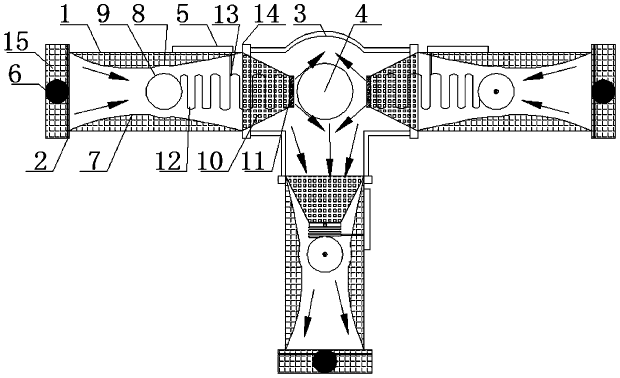
[0036] combine figure 1 and figure 2 , the air-adjustable three-way rectifier valve in this embodiment includes a fluid impact chamber 3 and three diversion pipes 1 that are respectively connected to the fluid impact chamber and have the same structure. The three diversion pipes form a "T" with the fluid impact chamber shaped structure.

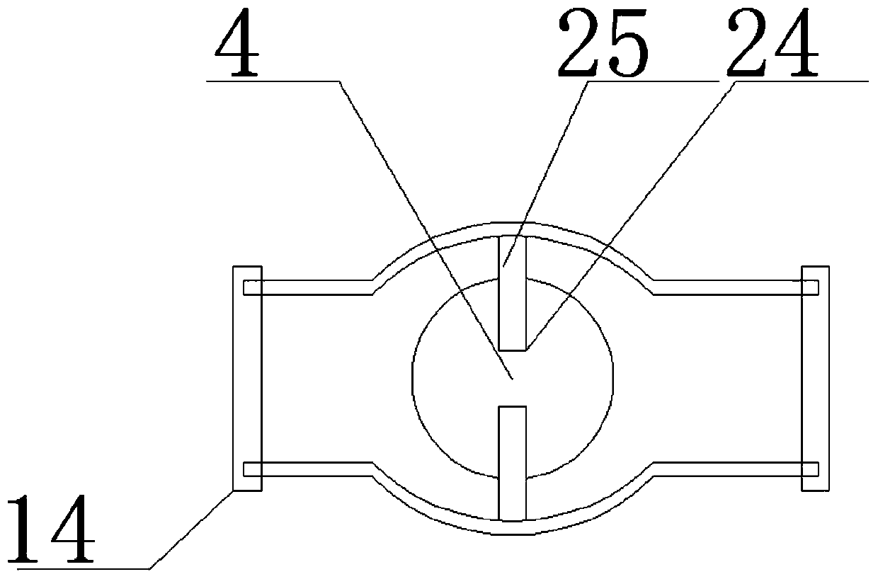
[0037] combine figure 1 , figure 2 and image 3, the fluid impact chamber is spherical, and there is a solid fluid impact ball 4 in the fluid impact chamber. The fluid impact ball passes through the connecting hole 24 provided on its outer wall and the connecting column 25 installed on the inner wall of the impact chamber. center of the room.

[0038] to combine figure 1 , figure 2 and Figure 4 to Figure 8 , the three diversion pipes 1 are respectively formed by docking the upper casing 27 of the diversion...


PUM


Abstract

The invention relates to an air-conditioning type three-way flow adjusting valve. The air-conditioning type three-way flow adjusting valve comprises a fluid impact chamber with a fluid impact ball inthe center and three guide pipelines which are correspondingly connected with the fluid impact chamber and have the same structure and are round and rectangular in the middle at two ends; the pipe cavity of the guide pipeline is formed in a shape from the center to the two ends from small to large, the connector end is provided with a filter screen and a flow probe, the central parts of the innerwalls of the upper shell and the lower shell of the guide pipeline are correspondingly provided with arc-shaped grooves which are transversely arranged and corresponds to each other, a cylindrical flexible air bag which can be tightly attached to the grooves after being expanded is arranged in the guide pipeline, and a funnel-shaped flexible anti-backflow nozzle is arranged in the guide pipeline between the flexible air bag and the fluid impact chamber. The inlet end of the anti-backflow nozzle is connected with the fluid impact chamber, and the outlet end of the anti-backflow nozzle is connected with a telescopic spring controlled by a shifting rod shifted by a shifting rod moving control device. The device has the beneficial effects that the guide is completed by the volume change of theflexible air bag, and the service life is long; the sealing performance is good, and the leakage amount is small; the response speed is quick; the flow of one of the outlet channels can be adjusted under the condition of keeping the total flow of the outlets unchanged; a plurality of flow adjusting valves can be simultaneously controlled through a computer control program, and fluid guide, flow adjusting, flow stopping and the like in a complex fluid pipe network can be accurately controlled.

Description

technical field [0001] The invention relates to a valve, in particular to an air-adjusted three-way rectifier valve. Background technique [0002] The rectifier valve is an important control component in the fluid delivery system, which has the functions of adjustment, diversion, and diversion. At present, most rectification valves are composed of one-way valves according to specific connection methods, relying on the characteristics of one-way flow and reverse closure of one-way valves to achieve the purpose of rectification. Due to structural problems, the rigid valve core and valve seat often have reduced sealing performance due to friction, impact and fluid dynamics during operation, resulting in large leakage and short service life; at the same time, due to their slow response speed, they cannot meet special working conditions. under the control requirements. Using this kind of rectifier valve to divert, rectify, and stop the flow of fluid at multiple nodes in the com...

Claims


Application Information

Patent Timeline
IPC IPC(8): F16K11/22F16K7/10F16K31/02
CPCF16K7/10F16K11/22F16K31/02
Inventor 张明乾李宗翔
Owner LIAONING TECHNICAL UNIVERSITY
Learn More