
A kind of on-site environment energy-saving control method

A technology for energy-saving control and on-site environment, which is applied in the direction of control input related to air characteristics, space heating and ventilation control input, heating mode, etc., which can solve energy waste, heavy management and maintenance workload, and inability to adjust multiple environmental adjustments in real time Equipment and other issues to achieve the effect of reducing waste, improving user experience, and reducing the workload of management and maintenance

Active Publication Date: 2021-08-03
HUBEI KAIMEI ENERGY TECH
View PDF8 Cites 0 Cited by
  • Summary
  • Abstract
  • Description
  • Claims
  • Application Information

AI Technical Summary

Problems solved by technology

[0004] The main purpose of the present invention is to provide an on-site environment energy-saving control method, aiming to solve the technical problems that multiple environmental adjustment devices cannot be adjusted in real time, the management and maintenance workload is large, and energy waste is serious

Method used


Image

  • A kind of on-site environment energy-saving control method
  • A kind of on-site environment energy-saving control method
  • A kind of on-site environment energy-saving control method

Examples


Embodiment Construction

[0043] It should be understood that the specific embodiments described here are only used to explain the present invention, not to limit the present invention.

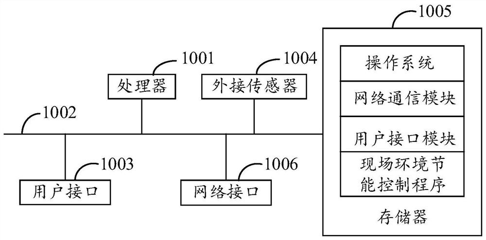
[0044] refer to figure 1 , figure 1 It is a schematic structural diagram of the on-site environment energy-saving control equipment for the hardware operating environment involved in the solution of the embodiment of the present invention.

[0045] Such as figure 1As shown, the on-site environment energy-saving control device may include: a processor 1001, for example, a central processing unit (Central Processing Unit, CPU), a programmable logic controller (Programmable Logic Controller, PLC), a communication bus 1002, a user interface 1003, External sensor 1004, memory 1005, network interface 1006. Wherein, the communication bus 1002 is used to realize connection and communication between these components. The user interface 1003 may include a display screen (Display) and an input unit such as a keyboard (Keyboa...


PUM


Abstract

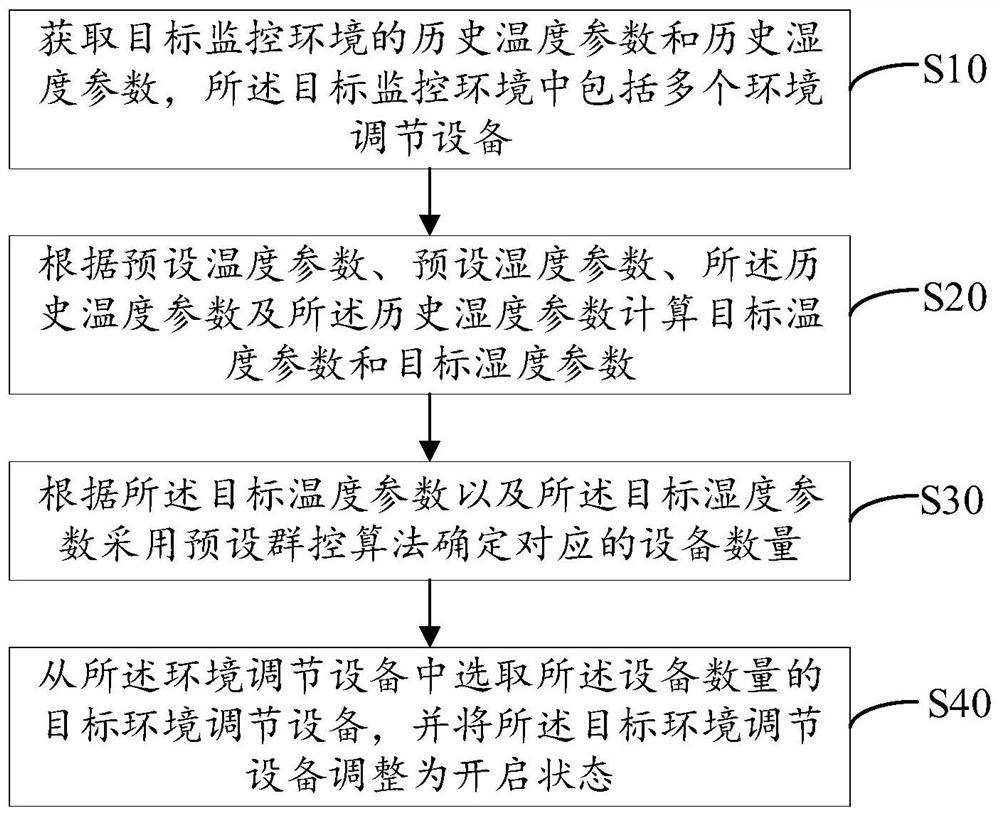
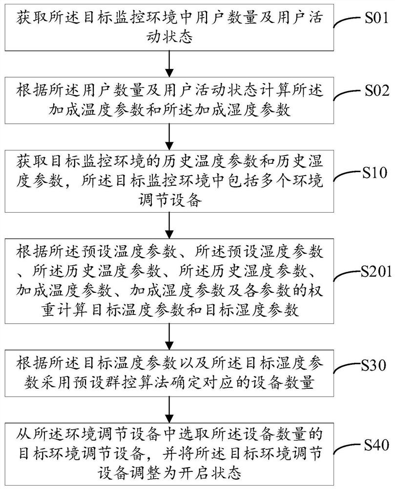
The present invention relates to the technical field of intelligent control, and discloses an on-site environment energy-saving control method. The method includes: acquiring historical temperature parameters and historical humidity parameters of a target monitoring environment, wherein the target monitoring environment includes a plurality of environmental adjustment devices; Set the temperature parameter, the preset humidity parameter, the historical temperature parameter and the historical humidity parameter to calculate the target temperature parameter and the target humidity parameter; according to the target temperature parameter and the target humidity parameter, use the preset group control algorithm to determine the corresponding The number of devices; select the target environment regulation device of the number of devices from the environment regulation devices, and adjust the target environment regulation device to the open state, and comprehensively adjust the target temperature parameters and target humidity parameters through multi-dimensional data to achieve real-time adjustment The purpose of multiple environmental conditioning equipment is to reduce the workload of management and maintenance, and also reduce the waste of energy.

Description

technical field [0001] The invention relates to the technical field of intelligent control, in particular to an on-site environment energy-saving control method. Background technique [0002] With the development of intelligent control technology, the concept of energy saving and environmental protection is becoming more and more popular. However, due to the design limitations of traditional air conditioners, the refrigeration host is in a low-load and low-efficiency operation state for a long time, and the cooling water temperature remains too high or low for a long time. If the temperature is too low, the ideal optimum temperature cannot be achieved. On the other hand, in actual operation, manual adjustment is usually required by the staff, which leads to heavy management and maintenance workload and high cost, and there are situations where equipment failures cannot be discovered in time, and manual operations cannot be comprehensive. Grasp the real-time dynamics of the o...

Claims


Application Information

Patent Timeline
Patent Type & Authority Patents(China)
IPC IPC(8): F24F11/89F24F11/64F24F11/58F24F110/10F24F110/20
CPCF24F11/58F24F11/64F24F11/89F24F2110/10F24F2110/20
Inventor 张军凯刘沛沛
Owner HUBEI KAIMEI ENERGY TECH
Learn More