High-low fin reinforced condensation heat exchange tube

A heat exchange tube and tube body technology, which is applied to evaporators/condensers, refrigerators, refrigeration components, etc., can solve the problems of improving heat exchange performance, insufficient heat exchange efficiency, and inability to fully utilize the surface tension of condensate, etc. Achieve the effect of reducing thermal resistance, improving heat transfer effect, and reducing thermal resistance

Pending Publication Date: 2019-11-08
JIANGSU CUILONG PRECISION COPPER TUBE CORP
View PDF1 Cites 1 Cited by
  • Summary
  • Abstract
  • Description
  • Claims
  • Application Information

AI Technical Summary

Problems solved by technology

For example, a condensing heat transfer tube disclosed in Chinese Patent Application Publication No. CN101813433A uses a fin top slotted fin structure, and the formed zigzag fins can thin or pierce the condensate film, which enhances condensation to a certain extent. However, due to the uniform height of the fins and the uniform distribution of the fin structure, the surface tension of the condensate cannot be fully utilized to improve the heat transfer performance, and the heat transfer efficiency is relatively not high enough

Method used


Image

  • High-low fin reinforced condensation heat exchange tube
  • High-low fin reinforced condensation heat exchange tube
  • High-low fin reinforced condensation heat exchange tube

Examples


Embodiment 1

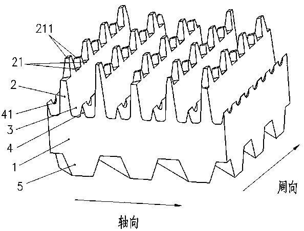
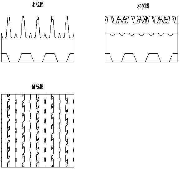
[0026] refer to figure 1 , figure 2 As shown, it shows a schematic structural view and three views of the first embodiment of a high and low fin enhanced condensation heat exchange tube of the present invention. In this preferred embodiment, the heat exchange tube includes a tube body 1 with an inner cavity, and the tube The outer surface of the body 1 is provided with primary outer fins 2 that are distributed in a spiral shape and are integrated with the tube body 1, and the space formed between the adjacent primary spiral outer fins 2 forms interconnected channels. 3 structure, the top of the first-stage spiral outer fin 2 is provided with first grooves 21 that are both interlaced and communicated with the channel 3, and the first grooves 21 are spaced apart along the thread extension direction of the first-stage spiral outer fin 2 Arranged so that the top of the primary helical outer fin 2 forms an uneven wing tip 211 structure.

[0027] The bottom of the channel 3 is pr...

Embodiment 2

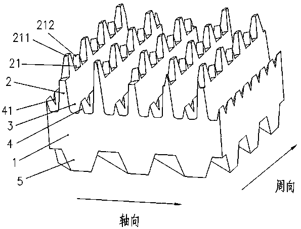
[0029] refer to image 3 , Figure 4 As shown, it shows a schematic structural view and three views of the second embodiment of a high-low fin enhanced condensation heat exchange tube of the present invention. In this preferred embodiment, its basic structure and principle are the same as those of the first embodiment, the difference is The cross-sectional profile of the second groove 41 of the heat exchange tube is V-shaped.

[0030] The present invention is a high and low fin enhanced condensation heat exchange tube, the first groove 21 on the top of the first-stage spiral outer fin 2 forms an uneven wing tip 211 structure, which is beneficial to destroy the surface tension of the condensed liquid film and make the liquid film Thinning, reducing thermal resistance, thereby achieving the effect of reducing the thickness of the liquid film and improving the condensation heat transfer. At the same time, the complex three-dimensional structure also increases the heat exchange ...


PUM


Abstract

The invention provides a high-low fin reinforced condensation heat exchange tube. The high-low fin reinforced condensation heat exchange tube comprises a tube body and first-stage outer fins in a spiral state, wherein the first-stage outer fins are of an integral structure and are in a spiral state, spaces between adjacent first-stage spiral outer fins form channel structures communicating with each other, and sharp secondary spiral outer fins are arranged at the bottoms of the channels; first grooves which are staggered with the channels and communicate with the channels are formed in the topof the first-stage spiral outer fins to form a fin tip structure with uneven height; and second grooves which are staggered with the channels and communicate with the channels are formed in the secondary spiral outer fins; and meanwhile, the inner surface of the tube body is provided with inner threaded ribs which extend spirally in the axial direction. The high-low fin reinforced condensation heat exchange tube has the advantages that the heat exchange surface area inside and outside the tube can be increased, a liquid film can be thinned by the high and low fin structure outside the tube, the liquid discharging speed of refrigerants on the surface of the fins is increased, the heat exchange effect of a condensation tube is improved, the internal thread rib structure in the tube is beneficial to improving the flowing state of fluid in the tube, and thus the effect of heat exchange between inside and outside of a reinforcing tube is achieved.

Description

technical field [0001] The invention belongs to the technical field of condensation heat exchange tubes in air-conditioning and refrigeration systems, and in particular relates to a high-low fin enhanced condensation heat exchange tube. Background technique [0002] The condensing heat exchanger is an essential component in the central air-conditioning system, and the condensing pipe is the core component of the condensing heat exchanger, and its heat transfer performance determines the performance of the condensing heat exchanger. In recent years, with the development of technology in the field of refrigeration and air conditioning, the continuous update of heat exchanger manufacturing technology has been promoted, and the design and manufacturing technology of heat exchange tubes for heat exchangers are also constantly updated and developed. [0003] The water-cooled condensers used in centrifugal and screw refrigeration units are mainly horizontal shell-and-tube heat exch...

Claims


Application Information

Patent Timeline
Patent Type & Authority Applications(China)
IPC IPC(8): F25B39/04
CPCF25B39/04
Inventor 金莉雯张春明邹锋包嘉峰
Owner JIANGSU CUILONG PRECISION COPPER TUBE CORP
Why Eureka
Try Eureka