Heating furnace portable type slag removal conveying device

A technology of conveying device and heating furnace, which is applied in descaling device, heat treatment furnace, lighting and heating equipment, etc., to achieve the effect of reducing manual transportation, speeding up cleaning efficiency and facilitating movement.

Pending Publication Date: 2019-11-08
浙江二十冶建设有限公司 +1
View PDF0 Cites 1 Cited by
  • Summary
  • Abstract
  • Description
  • Claims
  • Application Information

AI Technical Summary

Problems solved by technology

In order to reduce the labor intensity of workers, a special tool is needed for the slag removal work in the steel rolling heating furnace; however, due to the structural characteristics of the heating furnace, none of the mechanized chemical tools on the market can realize the slag removal operation in the heating furnace. Tools to reduce the load of manual slag removal in the heating furnace are very necessary

Method used


Image

  • Heating furnace portable type slag removal conveying device
  • Heating furnace portable type slag removal conveying device
  • Heating furnace portable type slag removal conveying device

Examples


Embodiment 1

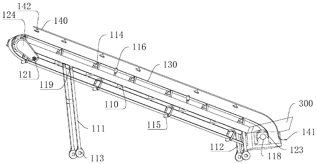
[0034] Such as Figure 1-3 Shown, a kind of belt transmission device is characterized in that, comprises:

[0035] Bracket 110 , the bracket 110 is a support frame from the entire belt transmission device 100 .

[0036] The driving device 120, the driving device 120 is arranged at both ends of the bracket 110, the driving device 120 provides power for the belt transmission device 100, and changes the direction of movement.

[0037] Conveyor belt 130, the conveyor belt 130 is arranged on the outside of the bracket 110, the two ends of the conveyor belt 130 are connected with the driving device 120, the conveyor belt 130 is the carrier of the main conveying object, and the driving device 120 provides power to drive the conveyor belt 130 around the bracket 110 rotates, and the object is transported from this end of support 110 to the other end of support 110.

[0038] The support 110 below is provided with the first moving leg 111 and the second moving leg 112, and the first mo...

Embodiment 2

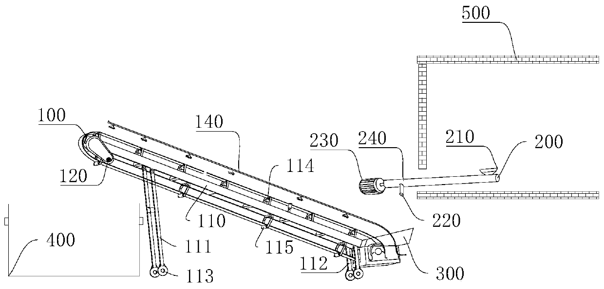
[0053] Such as figure 1 and Figure 4 Shown, a kind of belt transmission device 100 is characterized in that, comprises:

[0054] Bracket 110 , the bracket 110 is a support frame from the entire belt transmission device 100 .

[0055] The driving device 120, the driving device 120 is arranged at both ends of the bracket 110, the driving device 120 provides power for the belt transmission device 100, and changes the direction of movement.

[0056] Conveyor belt 130, the conveyor belt 130 is arranged on the outside of the bracket 110, the two ends of the conveyor belt 130 are connected with the driving device 120, the conveyor belt 130 is the carrier of the main conveying object, and the driving device 120 provides power to drive the conveyor belt 130 around the bracket 110 rotates, and the object is transported from this end of support 110 to the other end of support 110.

[0057] The support 110 below is provided with the first moving leg 111 and the second moving leg 112, ...


PUM


Abstract

The invention discloses a heating furnace portable type slag removal conveying device, and belongs to the technical field of heating furnace slag removal. The device solves the problems of low labor transportation efficiency, large workload and production delay. The heating furnace portable type slag removal conveying device comprises a belt conveying device, a furnace inner conveying device, a material plate and a recovery box. A complete conveying line in and out of a furnace is formed, the labor intensity is reduced., so that the efficiency is improved, a water spraying device is arranged above a conveying belt, in the running process, dust falling and cooling treatment can be carried out on accumulated slag on the conveying belt through the water spraying device, movable supporting legs and universal wheels are arranged under a support, the height of the support and the height difference of the two ends can be adjusted through the movable supporting legs to match with the height ofthe recovery box, meanwhile, the support can be folded when not used and can also be moved to any position through the universal wheels, and the heating furnace portable type slag removal conveying device has the advantages of being simple in structure, convenient to move and good in cooling and dustfall effects.

Description

technical field [0001] The invention relates to the technical field of slag removal for heating furnaces, in particular to a portable slag removal transmission device for heating furnaces. Background technique [0002] During the production process of the steel rolling heating furnace, more oxide scales are produced in the furnace. The continuous accumulation of oxide scales causes the furnace bottom to rise, which not only affects the reliable operation of the walking beam and reduces the production efficiency of the heating furnace, but also reduces the life of the furnace bottom material. Security risks. Slag accumulation is extremely unfavorable to production operation and equipment maintenance. It is necessary to stop the furnace for inspection and clean up the scale regularly. However, from the perspective of the overall planning of production efficiency, there is usually only one opportunity to clean the slag in the furnace once a year; Tools such as shovels and tr...

Claims


Application Information

Patent Timeline
Patent Type & Authority Applications(China)
IPC IPC(8): F27D3/15F27D25/00C21D9/70
CPCC21D9/70F27D3/1545F27D25/00
Inventor 王振平贾龙飞
Owner 浙江二十冶建设有限公司
Why Eureka
Try Eureka