Door flip device

A technology for turning over devices and door panels, which is applied to devices and coatings that apply liquid to surfaces, and can solve problems such as low work efficiency and damage to door panels.

Active Publication Date: 2021-05-11
重庆市佳禾家具制造有限公司
View PDF5 Cites 1 Cited by
  • Summary
  • Abstract
  • Description
  • Claims
  • Application Information

AI Technical Summary

Problems solved by technology

[0004] After one side of the door panel is painted, the operator needs to turn over the door panel. In the prior art, the way of turning over is to use manual turning. When the number of door panels processed is large, manual turning is used, and the work efficiency is not good. High, misoperation will also cause damage to the door panel

Method used


Image

  • Door flip device
  • Door flip device
  • Door flip device

Examples


Embodiment 1

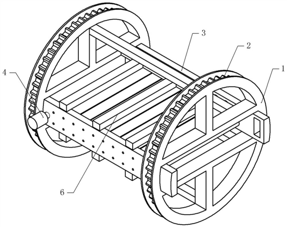
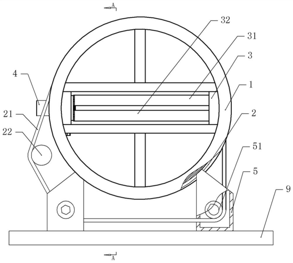
[0046] A door panel turning device, basically as attached figure 1 And attached figure 2 As shown, the runner 1 is included, the upper and lower parts of the runner 1 are welded with brackets, and an opening is formed between the two brackets.

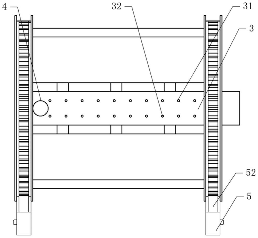
[0047] In this embodiment, there are two runners 1 , and the two runners 1 are arranged coaxially. Both sides of the two runners 1 are welded with connecting plates 3 , and the connecting plates 3 are arranged along the axial direction of the runners 1 . Between the two connecting plates 3 are rotatably connected a plurality of pairs of roller groups uniformly distributed along the length direction of the connecting plates 3 . The top and bottom of connecting plate 3 are all fixed with stabilizing plate 6 by fastening bolts, and the two ends of stabilizing plate 6 are respectively fixed two on connecting plate 3, and stabilizing plate 6 strengthens the stability of connecting plate 3.

[0048] There is a groove on the runner 1, the ...

Embodiment 2

[0057] The difference between embodiment two and embodiment one is that, as attached Figure 6 And attached Figure 7 As shown, one side of the inner side wall of any runner 1 is provided with a driving gear 11, the driving gear 11 is coaxial with the runner 1 and the driving gear 11 is fixed on the mounting base 9 through a connecting rod, and the right side of the driving gear 11 meshes There is a driven gear 7, the driven gear 7 and the driving gear 11 have a certain gear ratio, for example: 1:3, the driven gear 7 is coaxially fixed with a crankshaft 71, and the two ends of the crankshaft 71 are respectively connected to two runners in rotation. 1 The plate from which the inner side wall extends.

[0058] combined with Figure 6 As shown, the connecting plate 3 on the right side is horizontally slidably connected with a clamping tube 8 , which is sleeved on the outer periphery of the lower roller 32 , and the right side of the clamping tube 8 can abut against the bump of ...


PUM


Abstract

The invention relates to the technical field of door panel processing, and discloses a door panel turning device, which includes at least two runners, and two adjacent runners are respectively provided with connecting plates arranged in the axial direction of the runners; Between the connecting plates on the side, there are a number of pairs of roller groups uniformly distributed along the axial direction of the runner. For the sprocket, support seats are provided on both sides of the lower part of the runner, and a cavity with an upper opening is arranged in the support seat, the upper end of the support seat extends into the groove and the upper end of the support seat is slidingly connected with the side wall of the groove The cavity is provided with a tensioning wheel that is rotatably connected to the support seat, and one side of the running wheel is provided with a driving wheel, and the running wheel is provided with a chain set on the driving wheel, the tensioning wheel and the main sprocket, and the driving wheel Driven by drive motor. The invention has a simple structure, and the door panel is turned over to improve the working efficiency of turning over the door panel.

Description

technical field [0001] The invention relates to the technical field of door panel processing, in particular to a door panel turning device. Background technique [0002] The door panel, one of the house structures, its main function is to close the house. With the needs of social economy and house decoration, the processing requirements of door panels are getting higher and higher, such as: carving, painting and laminating on door panels. [0003] Taking door panel painting as an example, in order to improve the effect of door panel painting, one side of the door panel will be polished and smooth first, and then sent to the painting equipment for the first painting, after the paint on the surface of the door panel is dried, then the second brushing paint, improve the quality of the door panel paint surface, and obtain high-quality door panels. [0004] After one side of the door panel is painted, the operator needs to turn over the door panel. In the prior art, the way of ...

Claims


Application Information

Patent Timeline
Patent Type & Authority Patents(China)
IPC IPC(8): B05C13/02
CPCB05C13/02
Inventor 唐静
Owner 重庆市佳禾家具制造有限公司
Why Eureka
Try Eureka