Fracture traction reduction device

A traction reset and traction component technology, applied in the direction of fixator, external fixator, etc., can solve the problems of inability to adjust movement at any angle and position, poor flexibility in multi-angle adjustment, etc. High stability and stability

Inactive Publication Date: 2019-11-12
陈聚伍
View PDF0 Cites 3 Cited by
  • Summary
  • Abstract
  • Description
  • Claims
  • Application Information

AI Technical Summary

Problems solved by technology

[0003]Aiming at the problem that current fracture positioning and fixation devices have poor flexibility in multi-angle adjustment or cannot realize arbitrary angle and position adjustment and movement, the present invention provides a multi-angle fracture fixation device that is suitable for any fracture situation. The step-by-step compound adjustment reset device achieves fast and accurate docking of the fracture site, and has a high degree of restraint on the fracture site, so as to facilitate the smooth follow-up surgery on the fracture site

Method used


Image

  • Fracture traction reduction device
  • Fracture traction reduction device
  • Fracture traction reduction device

Examples


Embodiment 1

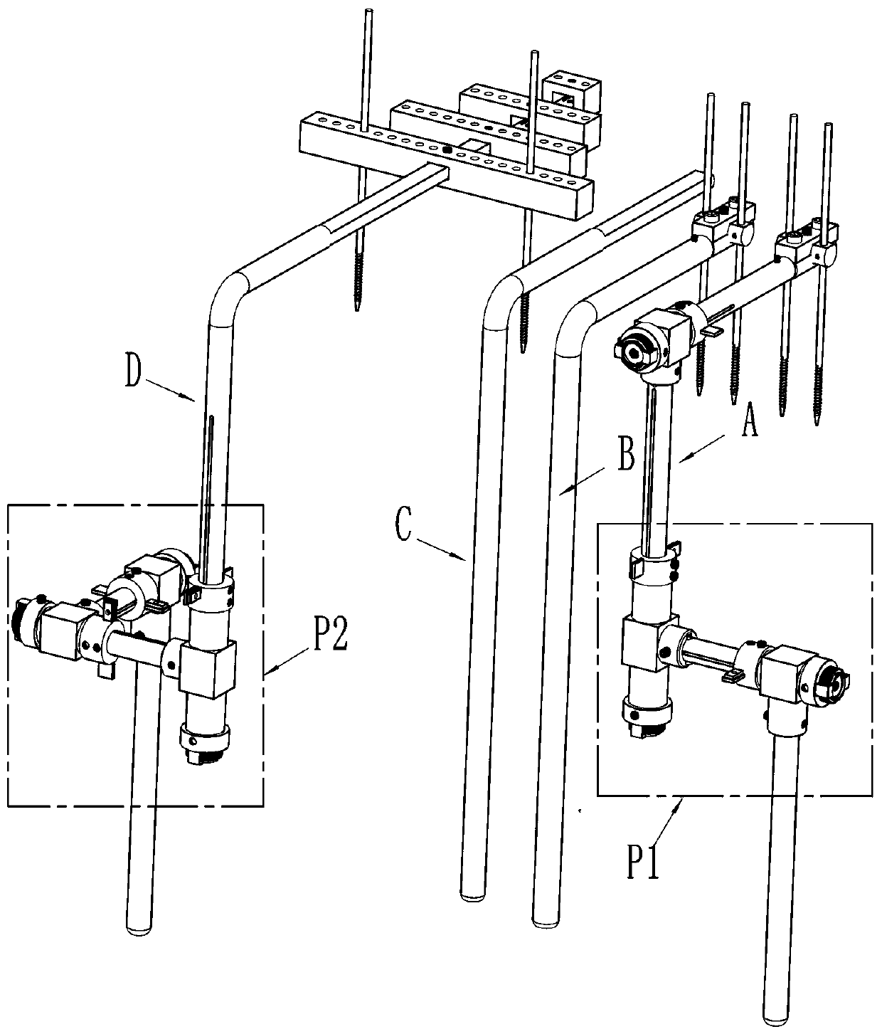
[0038] Embodiment 1: In this embodiment, the active adjustment mechanism is adopted as traction assembly A, and the passive adjustment mechanism is also adopted as traction assembly A.

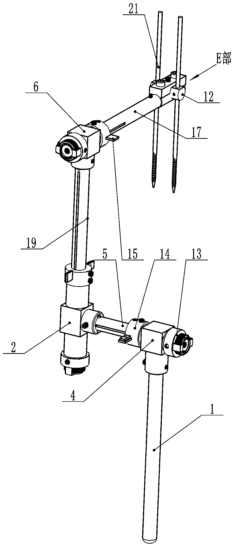
[0039] Such as image 3 As shown, the traction assembly A includes a three-dimensional adjustment mechanism P1, the bottom of the three-dimensional adjustment mechanism one is fixed, and the control end of the three-dimensional adjustment mechanism one fixes the Kirschner wire one. Specifically, the three-dimensional adjustment mechanism includes a first-level rod, that is, the vertical rod 1 , a second-level rod, that is, the longitudinal axis 5 , a third-level rod, that is, the vertical shaft 19 , and a fourth-level rod, that is, the horizontal shaft 17 . The upright pole is fixed on the bed frame or support (carrier) by the fixing parts, and the fixing parts are common locking parts in the field, or are fixed by more than two crossing bolts. Such as image 3 Among them, the upper end of t...

Embodiment 2

[0042] Embodiment 2: In this embodiment, the first Kirschner wire is fixedly installed as the traction assembly A by the active adjustment mechanism, and the second Kirschner wire is also fixedly installed by the traction assembly B by the passive adjustment mechanism.

[0043] The structure of the traction assembly A is the same as that of the traction assembly A in Embodiment 1, and will not be described in detail. The traction assembly B includes a vertical rod, the upper end of the vertical rod is connected with a flat rod in a horizontal direction, and the end of the flat rod is provided with an angle adjustment mechanism. The adjustment part fixes the two Kirschner wires.

[0044] The angle adjustment mechanism is located at the end of the horizontal axis, such as Figure 7-Figure 13 As shown, the angle adjustment mechanism is provided with a rotating Kirschner wire seat 12 at the end of the corresponding rod (ie, the horizontal axis) for installing the Kirschner wire. ...

Embodiment 3

[0045] Embodiment 3: In this embodiment, the first Kirschner wire is fixedly installed as the traction assembly A by the active adjustment mechanism, and the second Kirschner wire is also fixedly installed by the traction assembly B by the passive adjustment mechanism.

[0046] The structure of the traction assembly A is the same as that of the traction assembly A in Embodiment 1, and will not be described in detail. The traction assembly B includes a vertical rod, the upper end of the vertical rod is connected with a flat rod in a horizontal direction, and the end of the flat rod is provided with an angle adjustment mechanism. The adjustment part fixes the two Kirschner wires.

[0047] The angle adjustment mechanism is located at the end of the horizontal axis, and the angle adjustment mechanism is provided with a rotating and rotating Kirschner wire seat 12 at the end of the corresponding rod, such as Figure 17 As shown, the slidable and rotatable Kirschner wire holder 12 i...


PUM


Abstract

The invention discloses a fracture traction reduction device, which includes an active adjustment mechanism and a passive adjustment mechanism. The adjustment ends of the two adjustment mechanisms arerespectively fixedly installed with a Kirschner wire 1 and a Kirschner wire 2, and Kirschner wire 1 and the Kirschner wire 2 are respectively fixed at a distal end and a proximal end to a fracture site, the Kirschner wire 1 and the Kirschner wire 2 are respectively adjusted through the active adjustment mechanism and/or the passive adjustment mechanism to match for butt joint with the distal andproximal ends of the fracture site. The movement and angle adjustment make the fractures at the distal and proximal ends of the fracture site to be corresponded, and then the reset butt joint and fixation can be realized. An adjustment method of the invention is simple and easy to learn, the accuracy is very high, and the difficulty and inaccuracy of the operation are reduced. After simple training, the device is suitable for doctors at all levels to use, and also provides a basis for standardized operation of fracture positioning.

Description

technical field [0001] The invention belongs to the technical field of fracture positioning and fixing devices, and in particular relates to a fracture site reduction device capable of accurately performing multi-step compound adjustment and fixation. Background technique [0002] Femoral shaft fractures and distal femoral fractures are common clinical fractures. Surgical treatment is the preferred treatment method. Before intramedullary nailing and bone plate fixation, the two ends of the fracture site need to be reduced, docked and fixed. Traction is an important means of reducing femoral fractures and restoring the length of lower limbs. At present, the retractors used in various hospitals for lower extremity fracture patients mainly include a traction rope and a pulley. One end of the traction rope is connected to the bracket at the fracture site, and the other end bypasses the pulley to hang weights. The number of weights can be manually increased or replaced. The wei...

Claims


Application Information

Patent Timeline
Patent Type & Authority Applications(China)
IPC IPC(8): A61B17/66
CPCA61B17/66A61B17/6425
Inventor 陈聚伍
Owner 陈聚伍
Why Eureka
Try Eureka