
Full-automatic male pin solder cup milling machine

A milling machine, fully automatic technology, applied in the direction of milling machine equipment, milling machine equipment details, metal processing equipment, etc., can solve the problems of low efficiency and labor time, and achieve the effect of improving work efficiency, high practicability, and convenient operation

Pending Publication Date: 2019-11-12
HIGO TECH (SUZHOU) CO LTD
View PDF0 Cites 0 Cited by
  • Summary
  • Abstract
  • Description
  • Claims
  • Application Information

AI Technical Summary

Problems solved by technology

This process is currently processed by manual or semi-automatic methods in the market (not only takes up labor time, but also is inefficient)

Method used


Image

  • Full-automatic male pin solder cup milling machine

Examples


Embodiment

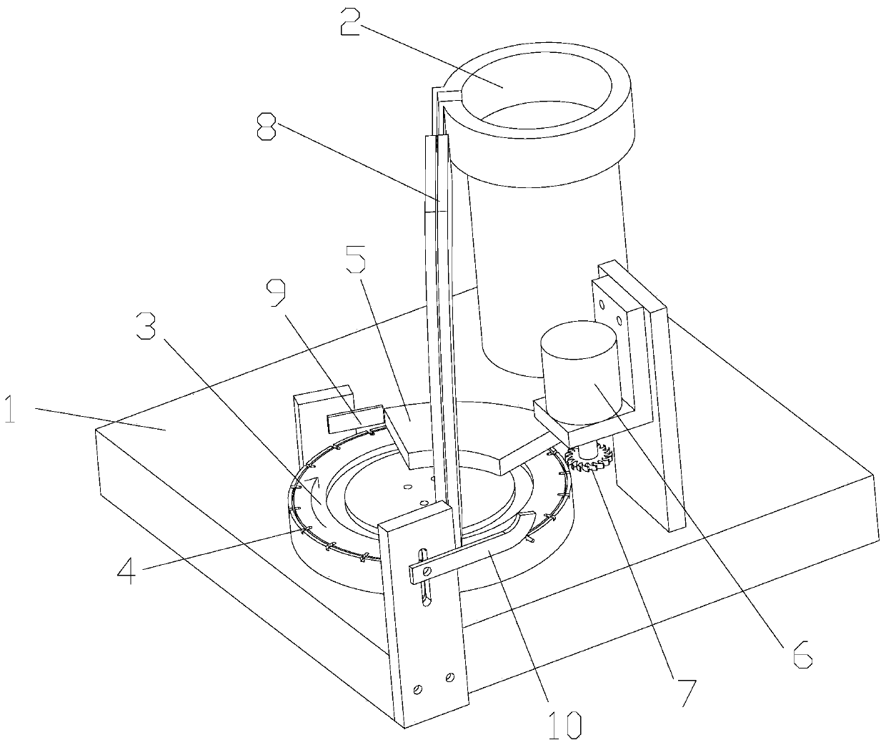
[0025] Example: such as figure 1 As shown, a fully automatic male pin welding cup milling machine includes a base 1 on which a vibrating plate 2 and a rotating disc 3 are arranged. The vibrating disc 2 and the rotating disc 3 are connected through an arc track 8, and the arc The feed port of the track 8 is located in the vibrating plate 2, and the discharge port of the arc track 8 is close to the round edge of the upper surface of the rotating disc 3, and at the same time, it is evenly circled around the round edge of the upper surface of the rotating disc 3. A number of card slots 4 are provided; one side of the rotating disc 3 is provided with a milling device, the milling device includes a cutter 7, a rotating shaft and a rotating motor 6, the cutter 7 is connected to the rotating motor 6 through a rotating shaft, and the cutter 7 and the card slot 4 are in the same Horizontal position; the main working process of the fully automatic male pin welding cup milling machine de...

Embodiment approach

[0027] The shape of the fixed disk 5 is a non-circular arc shape, and the position of the fixed disk 5 corresponds to the position of the milling device; the function of the fixed disk 5 is to position and fix the male needle at the milling position, Therefore, the shape and size of the fixed disk 5 need not be the same as that of the rotating disk 3 , it only needs to be a non-circular arc shape.

[0028] A positioning plate 9 is arranged on one side of the rotating disk 3, and the positioning plate 9 and the slot 4 are at the same horizontal position. According to the running track of the slot 4 on the rotating disk 3, the positioning plate 9 is located in the upper direction of the tool 7; The function of the positioning plate 9 is that when the male needle enters the slot 4, the position may not be correct. The positioning plate 9 can position the male pin in the slot 4 in time, because the positioning work needs to be done before the milling work, so The positioning plate...


PUM


Abstract

The invention relates to a full-automatic male pin solder cup milling machine. The machine comprises a base which is provided with a vibrating plate and a rotary moving plate, wherein the vibrating plate communicates with the rotary moving plate by a circular arc track, a feeding port of the circular arc track is located in the vibrating plate, a discharge port of the circular arc track is closelyattached to the rounded edge portion of the upper surface of the rotary moving plate, and a plurality of clamping slots are uniformly formed around the rounded edge portion of the upper surface of the rotary moving plate; and a milling device is arranged on one side of the rotary moving plate, and comprises a cutter, a rotating shaft and a rotating motor, the cutter is connected with the rotatingmotor by the rotating shaft, and the cutter is at the same horizontal position as the clamping slots. The full-automatic male pin solder cup milling machine designed by the scheme satisfies the current male pin milling precision, improves the overall working efficiency by adopting the continuous operating clamping structure and the non-stop automatic feeding structure, and also meets the dimensional accuracy of milling.

Description

technical field [0001] The invention belongs to the technical field of mechanical automation, and in particular relates to a fully automatic male pin welding cup milling machine. Background technique [0002] In the production process of the existing connectors, the male terminal pins (hereinafter referred to as "male pins") and female terminal sockets (hereinafter referred to as "female holes"), which are used as connectors for electrical conductivity, are necessary parts, and the amount is huge. [0003] Each male pin needs to be milled with a standard size land as a soldering location for subsequent wires. At present, enterprises in the market use manual or semi-automatic processing of this process (not only takes up man-hours, but also is inefficient). [0004] As the market demand for connectors continues to increase, the production efficiency and labor requirements of connector manufacturers are also facing severe challenges. How to use fewer people, high quality, and...

Claims


Application Information

Patent Timeline
IPC IPC(8): B23C3/00B23Q7/00B23Q7/02B23Q7/08H01R43/16
CPCB23C3/00B23Q7/00B23Q7/08B23Q7/02H01R43/16
Inventor 王峰
Owner HIGO TECH (SUZHOU) CO LTD
Learn More