Wood panel drilling device convenient to control punching spacing

A technology of drilling device and wood plate, applied in fixed drilling machine and other directions, can solve the problems of low precision and inconvenient control of the distance between two holes, achieve high precision, easy to control the distance of drilling, realize front and rear, left and right moving effect

Inactive Publication Date: 2019-11-12
杨钊銮
View PDF0 Cites 1 Cited by
  • Summary
  • Abstract
  • Description
  • Claims
  • Application Information

AI Technical Summary

Problems solved by technology

However, when the existing wood panel drilling device needs to punch the second hole after the first ...

Method used


Image

  • Wood panel drilling device convenient to control punching spacing
  • Wood panel drilling device convenient to control punching spacing
  • Wood panel drilling device convenient to control punching spacing

Examples


Embodiment 1

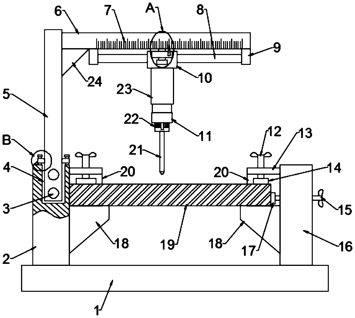
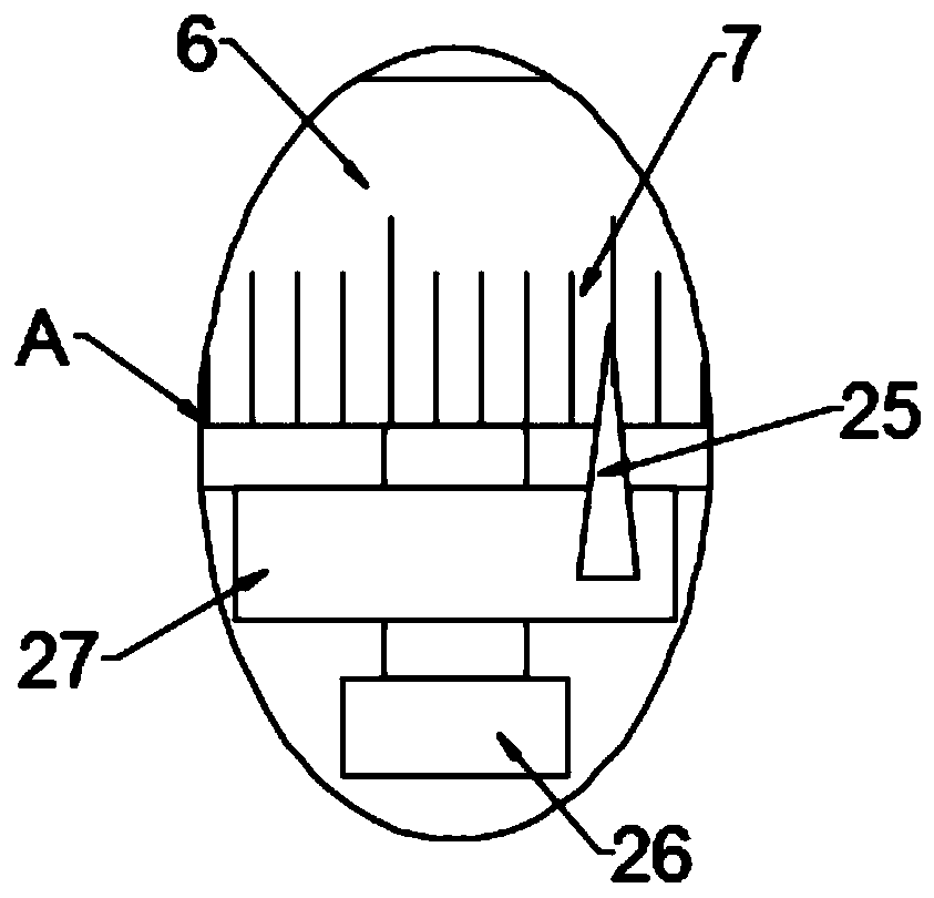
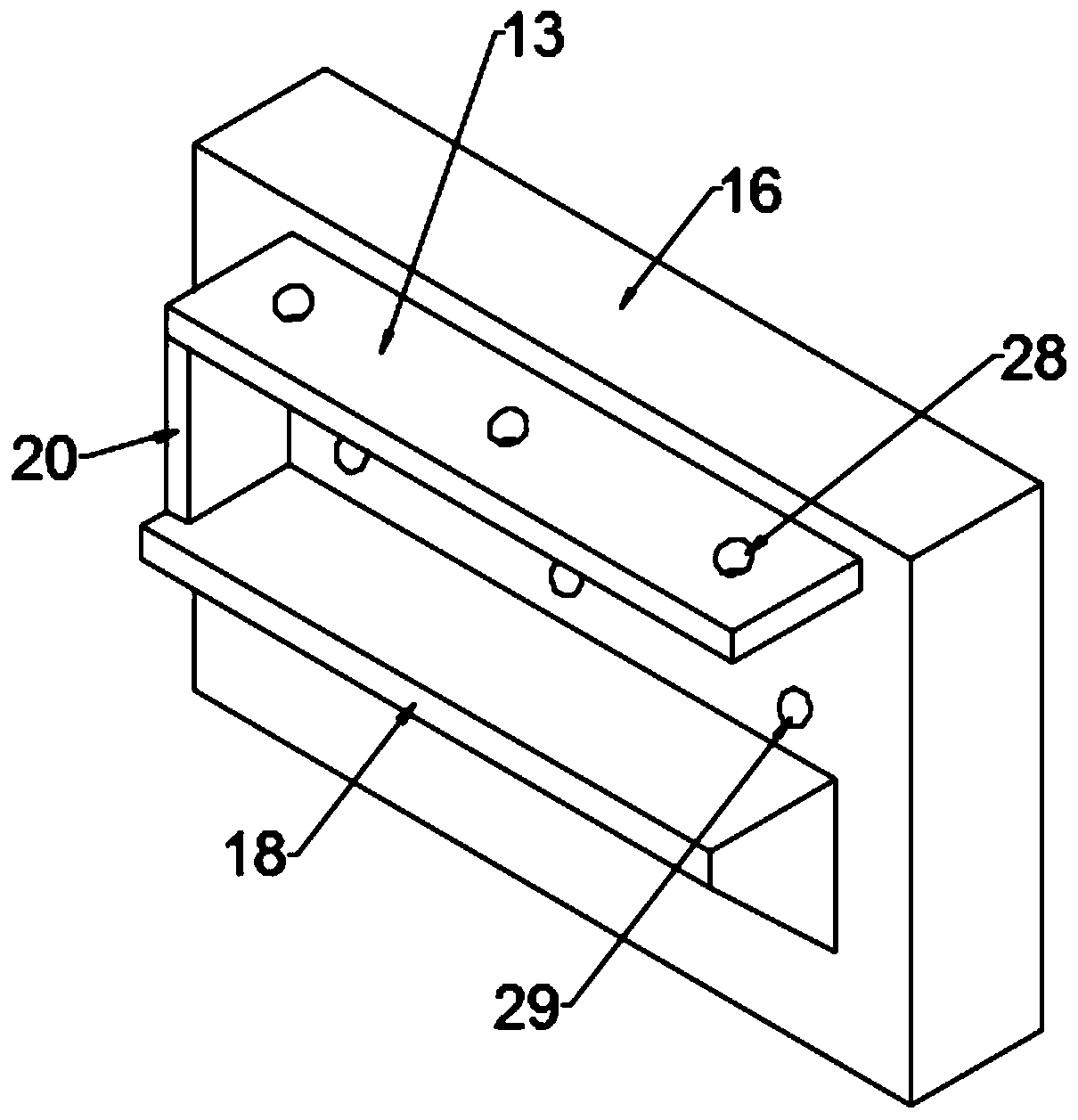
[0033] see Figure 1-5 , in the embodiment of the present invention, a kind of wood board drilling device that is convenient to control punching pitch, comprises base plate 1 and motor 22, and the output shaft of motor 22 is connected with drill rod 21; Said base plate 1 is provided with left side plate 2 And right side plate 16, supporting plate 18 and top plate 13 are all installed on the inboard surface of left side plate 2 and right side plate 16, be provided with tailgate 20 between the rear end of supporting plate 18 and top plate 13, so The top plate 13 is provided with a top extruding assembly, and the right side plate 16 is provided with a side extruding assembly; from the front opening of the top plate 13 and the supporting plate 18, the wooden board 19 to be punched is put into the supporting plate 18 and make the rear side of the wooden board 19 contact with the tailgate 20, press the wooden board 19 to the left through the side extrusion assembly, make the left si...

Embodiment 2

[0049] see Figure 6 , in the embodiment of the present invention, a kind of plank drilling device that is convenient to control the punching pitch, differs from embodiment 1 in that the bottom of the bottom plate 1 is provided with a wheel seat 38 and a horizontal plate 39, and the bottom of the wheel seat 38 Moving wheel 37 is installed, and strut bar 35 is threadedly installed on cross plate 39, and the bottom rotation of support bar 35 is provided with support foot 36, and the side of left side plate 2 is fixed with push rod 34; Screw thread fits, and rotating support bar 35 can drive support pin 36 to move up and down, utilize support pin 36 to be able to support the wood panel drilling device that this is convenient to control punching pitch when punching, after punching is finished, rotate support bar 35 to make support pin 36 breaks away from ground, is convenient to move this wood panel drilling device that is convenient to control punching pitch by support bar 35 and...


PUM


Abstract

The invention relates to the technical field of wood processing, in particular to a wood panel drilling device convenient to control a punching spacing. The wood panel drilling device convenient to control the punching spacing comprises a bottom plate and a motor, wherein a drill rod is connected to an output shaft of the motor; a left side plate and a right side plate are arranged on the bottom plate; a bearing plate and a top plate are arranged on the inner side surfaces of the left side plate and the right side plate; a back shield is arranged between the back ends of the bearing plate andthe top plate; a top part extruding assembly is arranged on the top plate; and a side part extruding assembly is arranged on the right side plate. The wood panel drilling device convenient to controlthe punching spacing further comprises a control mechanism for controlling the movement distance of the drill rod. According to the wood panel drilling device convenient to control the punching spacing, the front-and-back movement distance of the drill rod can be intuitively observed through a second pointer and a second scale mark, and the left-and-right movement distance of the drill rod can beintuitively observed through a first pointer and a first scale mark, so that the drill rod can move front and back as well as left and right, the movement distance of the drill rod is conveniently controlled, the punching spacing is further conveniently controlled, and the precision is high.

Description

technical field [0001] The invention relates to the technical field of wood processing, in particular to a wood plate drilling device which is convenient for controlling the punching distance. Background technique [0002] In the process of wood processing, drilling wood boards is one of the processes. However, when the existing wood panel drilling device needs to punch the second hole after punching the first hole, the distance between the two holes is inconvenient to control and the accuracy is not high. In view of the above problems, the present invention proposes a wood panel drilling device that is convenient for controlling the punching pitch. Contents of the invention [0003] The object of the present invention is to provide a wood panel drilling device that is convenient for controlling the punching pitch, so as to solve the problems raised in the above-mentioned background technology. [0004] To achieve the above object, the present invention provides the foll...

Claims


Application Information

Patent Timeline
IPC IPC(8): B27C3/02
CPCB27C3/02
Inventor 不公告发明人
Owner 杨钊銮
Why Eureka
Try Eureka