
Modular differential settlement accurate control device

It is a technology of precise control and differential settlement, which is applied to the field foundation soil survey, roads, roads, etc., and can solve the problems such as the inability to simulate the deformation response of weak strata and the uneven settlement of the subgrade surface.

Pending Publication Date: 2019-11-12
GUILIN UNIV OF ELECTRONIC TECH
View PDF1 Cites 11 Cited by
  • Summary
  • Abstract
  • Description
  • Claims
  • Application Information

AI Technical Summary

Problems solved by technology

The patent with the publication number CN102914632A discloses a multifunctional geotechnical model test box, which can test 20 kinds of soil arch effect demonstrations with different pile distance ratios, pile-supported embankment filler particle soil arch effects, and composite foundation pads under rigid foundations. The layer effect simulation test, and the differential settlement achieved by this kind of test device is mostly the overall movement, the settlement area has no relative displacement with each other, and the settlement mode only depends on the active lifting of the lower support, which cannot truly simulate the deformation response of the weak ground under the upper load and the pile Scenarios such as differential settlement of bearing embankment and uneven settlement of subgrade surface

Method used


Image

  • Modular differential settlement accurate control device
  • Modular differential settlement accurate control device
  • Modular differential settlement accurate control device

Examples


Embodiment

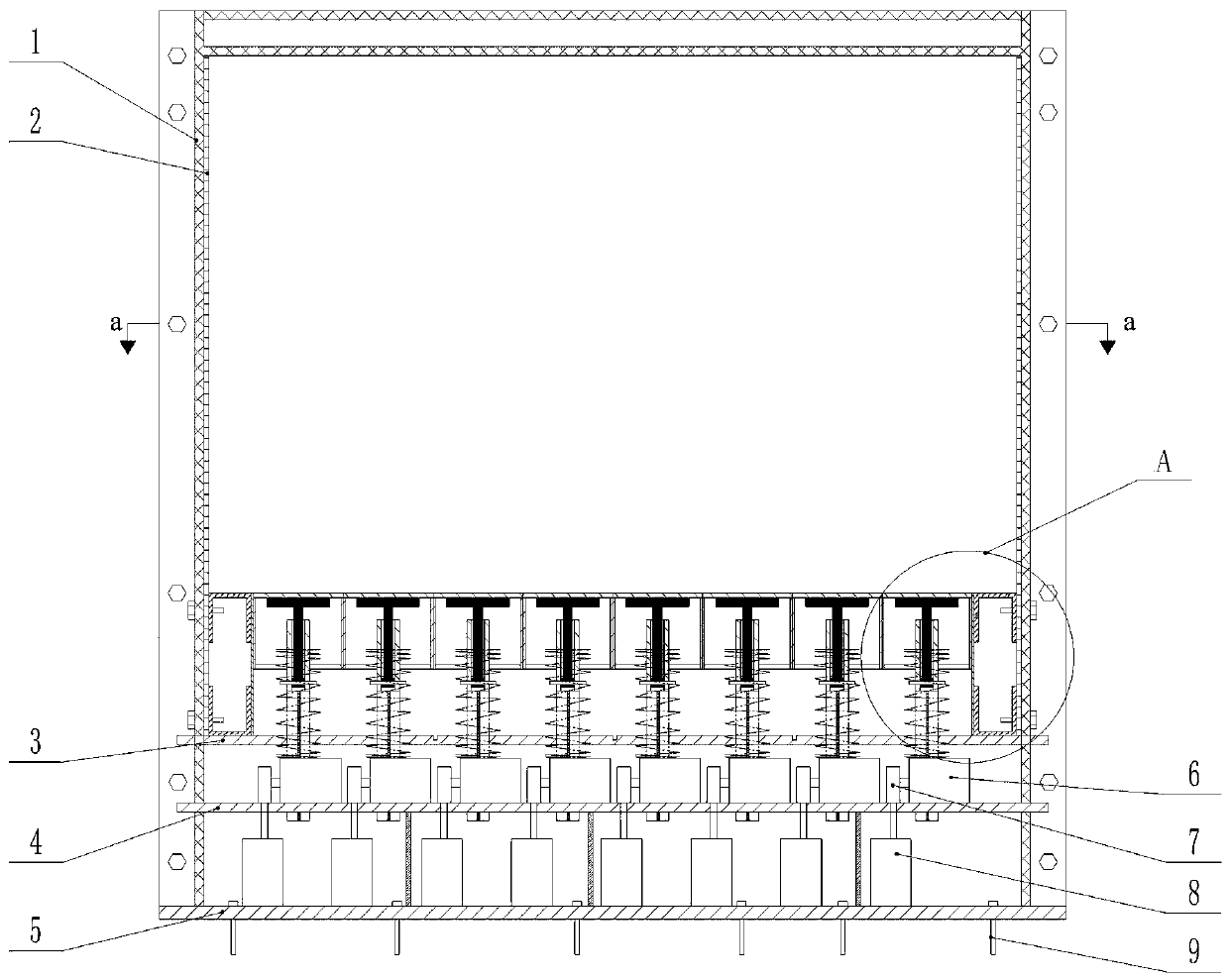
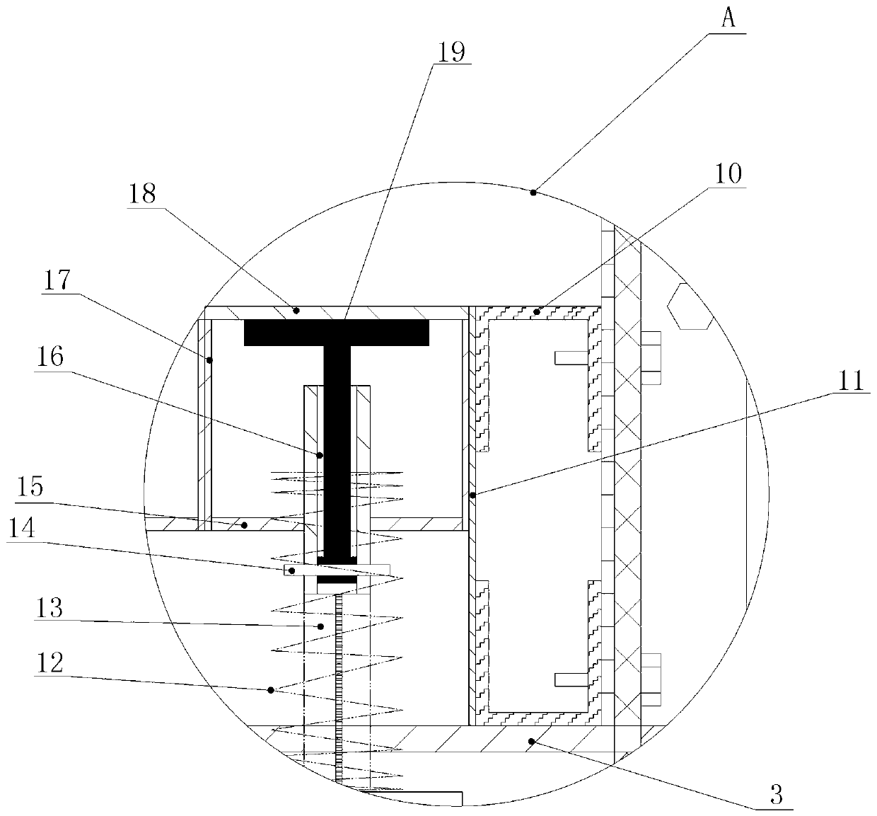
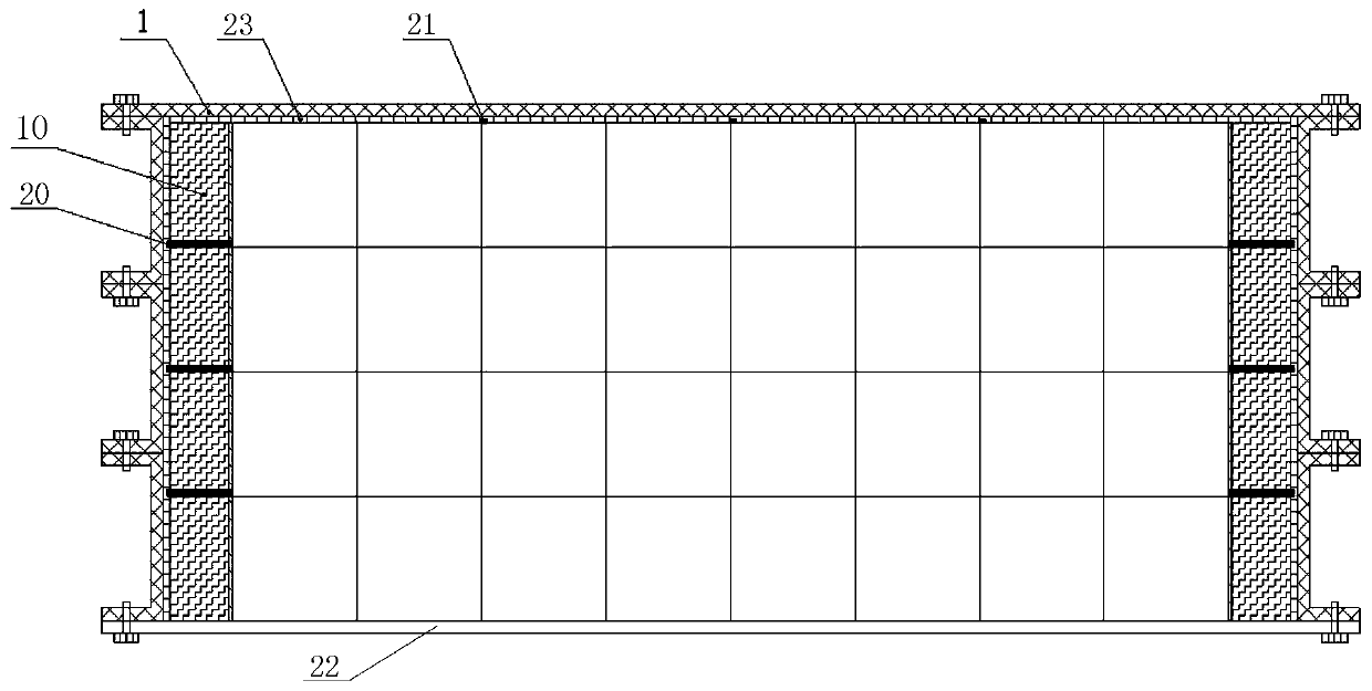
[0034] Such as figure 1 , figure 2 , image 3 Shown:

[0035] A modular differential settlement precision control device, including a model box frame 1, the size of the model box frame 1 (length × width × height) is 2000mm × 850mm × 2000mm, and the bottom plate 5 of the model box frame 1 is provided with 8× 4 variable speed motors 8, the first support plate 4 is fixed on the top of the variable speed motor 8, and the upper surface of the first support plate 4 is correspondingly provided with 8×4 screw lifters 6, and the output shaft of each variable speed motor 8 passes through the first support The plate 4 is connected to the corresponding screw lifter 6 through the diverter 7, the second support plate 3 is fixed above the screw lifter 6, the upper surface of the second support plate 3 is covered with a test box 2 with upper and lower ends opening around it, and the test box 2 The size (length×width×height) is 1800mm×800mm×1200mm. Two rows of side piers 10 are fixed on bo...


PUM

PropertyMeasurementUnit
Gap widthaaaaaaaaaa
Widthaaaaaaaaaa
Widthaaaaaaaaaa

Abstract

The invention discloses a modular differential settlement accurate control device, including a model box frame. A variable speed motor is arranged on the base plate at the bottom of the model box frame, a first support plate is fixed on the top of the variable speed motor, screw lifts are correspondingly arranged on the upper surface of the first support plate, the output shaft of the variable speed motor passes through the first support plate and is connected to the corresponding screw lifts through a steering device, a second support plate is fixed on the top of the screw lifts, a test box covers on the periphery of the upper surface of the second support plate, two rows of side piers are fixed on both sides of the upper surface of the second support plate in the test box, modular movable units are arranged between the two rows of side piers, the lower ends of the modular movable units are connected with the screw lifts through the second support plate, and the upper surfaces of themodular movable units are paved with packing to be tested; and the variable speed motor is connected with an outside control system. The device can simulate actual deformation modes of a soft stratumunder the upper load, and can also realize geotechnical tests such as differential settlement of a pile-supported embankment and uneven settlement of a subgrade surface at the same time.

Description

technical field [0001] The invention relates to a geotechnical model test device, in particular to a modular differential settlement precision control device for a geotechnical model test. Background technique [0002] For differential settlement geotechnical tests, the activity of the subsidence zone is often a single action through the active lowering of the lower support to drive the settlement of the upper filler in the subsidence zone, and the displacement of the rigid connection in the subsidence zone is uniform, which cannot truly simulate the deformation response of the weak ground under the upper load and the pile bearing capacity. Differential settlement of type embankment, uneven settlement of subgrade surface and other scenarios. [0003] Products similar to the present invention mainly include designs of various geotechnical model boxes for studying soil arching effects, and are mainly used for soil arching effect demonstration class geotechnical tests. The pat...

Claims


Application Information

Patent Timeline
IPC IPC(8): E02D1/00E01C3/00
CPCE02D1/00E01C3/00
Inventor 吴迪吴建建赵阳张耀文李晓
Owner GUILIN UNIV OF ELECTRONIC TECH
Learn More