Reciprocating impact oblique tooth discharging shovel of reciprocating impact mining machine

A technology of excavator and helical teeth, which is applied in the field of reciprocating impact helical tooth discharge shovel of reciprocating impact excavators, can solve the problems of difficult discharge and blanking, inability to reciprocate impact, high failure rate, etc., and achieve the goal of reducing shaking and improving impact efficiency Effect

Pending Publication Date: 2019-11-12
刘素华
View PDF0 Cites 0 Cited by
  • Summary
  • Abstract
  • Description
  • Claims
  • Application Information

AI Technical Summary

Problems solved by technology

[0002] In the process of the existing reciprocating impact mining machine impacting rock walls, coal walls, copper ore, iron ore, etc., because the diameter of the front end of the impact head is small and the diameter of the rear end is large, the impact head has no discharge structure, resulting in the materials washed down by the front end being crushed. The large impact head at the rear end is on the material wall to form a more solid material surface. Due to the large diameter of the impact head and the high resistance, the reciprocating impact head cannot reciprocate impact on the material wall, etc. Frequent reciprocating impacts of more than tens of tons often occur The reaction force caused the motor or motor that drives the reciprocating impact to be overloaded and damaged, etc. Although later, a variety of impact teeth were set around the impact rod of the impact head, because the impact rod is surrounded by teeth, forming a small diameter in the front and a larger diameter in the rear. Even if it hits soft rock or soft coal, because the front of the impact head is small and the rear is large, and because the teeth of the impact head are set in the same direction front and rear, the impact teeth are set parallel to the sides of the impact teeth, and the wall of the impact material is very short. Within a short period of time, the gap between the teeth of the impact head is small in front and large in the back, which means that the material cannot flow out, causing the subsequent falling materials to be continuously crowded between the teeth of the impact head, so that the entire impact head forms a larger mushroom head impact. The impact head makes the material wall form a larger and more solid material surface because there is no discharge space. The impact head impacts again. The more impact the material surface becomes, the harder the material surface is. The increasing resistance makes it difficult to discharge and drop the material on the impact head on the material wall. The material surface does not fall, but the impact head is clenched, and the impact head is pulled off the excavator, so that the reciprocating impact excavator consumes high energy, takes a long time, has low efficiency, high failure rate, and even cannot work normally at all, let alone reach Estimated production target, in order to solve the above problems, the present invention proposes a reciprocating impact mining machine reciprocating impact helical tooth discharge shovel

Method used


Image

  • Reciprocating impact oblique tooth discharging shovel of reciprocating impact mining machine
  • Reciprocating impact oblique tooth discharging shovel of reciprocating impact mining machine
  • Reciprocating impact oblique tooth discharging shovel of reciprocating impact mining machine

Examples


Embodiment 1

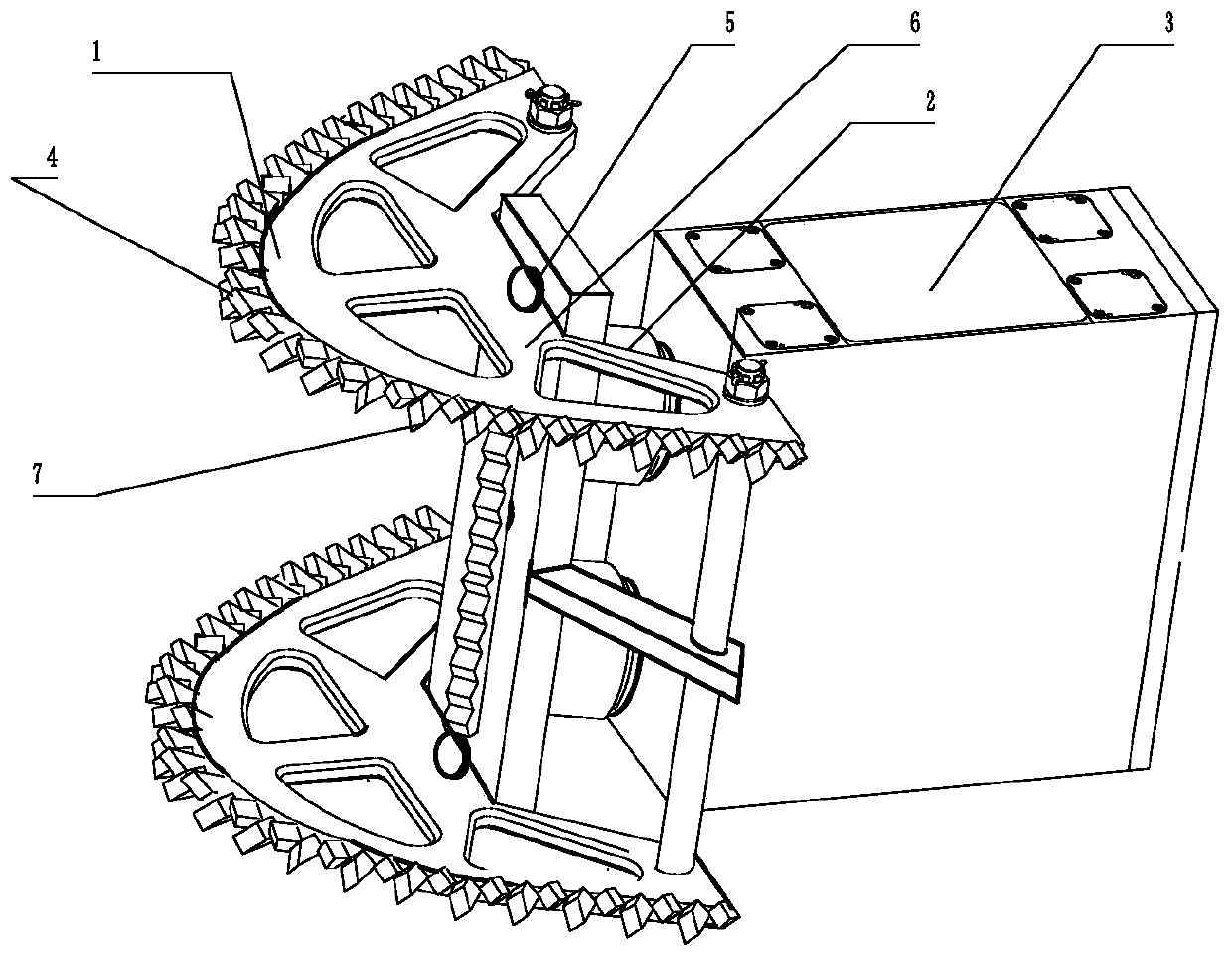
[0071] Such as figure 1 As shown, a reciprocating impact excavator reciprocating impact helical tooth discharge shovel includes a reciprocating impact box and a reciprocating impact helical tooth discharge shovel 1, and the reciprocating impact box includes a reciprocating impact box 3, a reciprocating impact power part and a reciprocating impact guide 2 etc., the reciprocating impact power part is arranged in the reciprocating impact box 3, and the reciprocating impact power part is supported by the reciprocating impact box 3 to drive the reciprocating impact guide 2, and one end of the reciprocating impact guide 2 extends out of the reciprocating impact box 3, and the reciprocating impact The helical tooth discharge shovel 1 includes the main tooth seat 5, the main punch tooth 4, the side discharge tooth wing plate 6 and the side discharge helical tooth 7, etc., and the main tooth seat 5 is arranged on the reciprocating impact mechanism extending outside the reciprocating imp...

Embodiment 2

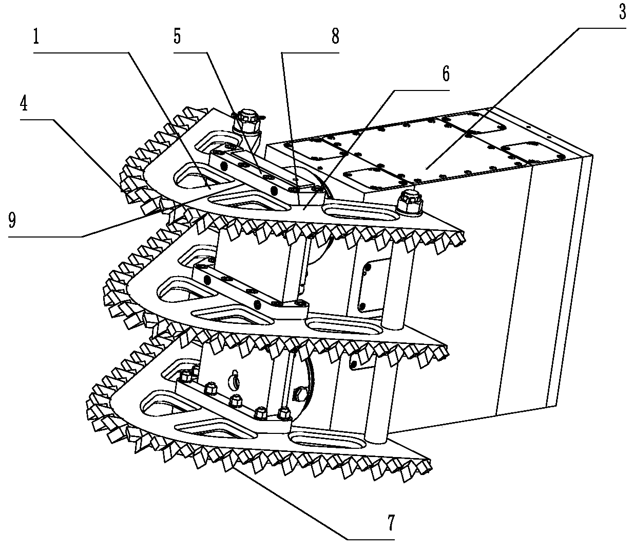
[0077] Such as figure 2 As shown, a reciprocating impact excavator reciprocating impact helical tooth discharge shovel, when the main gear seat 5 and the main punch tooth 4 are connected separately, the upper part of the side discharge tooth wing plate 6 protrudes from the top of the main tooth seat 5 and there is a side wing plate The anti-rotation surface 8, the main punch tooth 4 is set on the main gear seat 5 to fasten the side wing plate anti-rotation surface 9 and the side wing plate anti-rotation surface 8 to prevent the main punch tooth 4 from rotating, the main punch tooth 4 and the main tooth seat 5 pass through the cone The surface buckles, and the anti-return part only prevents the main punching tooth 4 from falling off in the main tooth seat 5 because the anti-rotation surface 8 of the side wing plate is not subjected to rotation and shearing, and the anti-rotation surface 8 of the side wing plate has a righting effect on the main punching tooth 4.

[0078] The m...

Embodiment 3

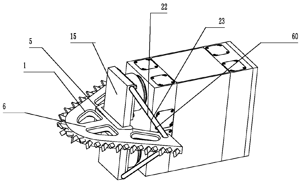
[0081] Such as image 3 As shown, the reciprocating impact helical tooth discharge shovel 1 also includes a reciprocating impact shovel plate 15. When a main tooth seat 5 is provided, a side discharge tooth wing plate rotation member 22 is set on the side discharge tooth wing plate 6. When When the rotary part 22 of the side discharge tooth flap is connected separately with the side discharge tooth flap 6, one end of the rotary part 22 of the side discharge tooth flap is connected with the side discharge tooth flap 6, and the other end is connected with the reciprocating impact shovel The plate 15 is connected, the side discharge tooth flap rotation part 22 is connected with the side discharge tooth flap through the rod perforation sleeve 23, the side discharge tooth flap rotation part 22 includes the rod perforation sleeve stop flap rotation part 60 , The side discharge tooth flap rotation member 22 prevents the side discharge tooth flap 6 from rotating, and prevents the side...


PUM


Abstract

The invention relates to the field of mining machinery, in particular to a reciprocating impact oblique tooth discharging shovel of a reciprocating impact mining machine. The reciprocating impact oblique tooth discharging shovel of the reciprocating impact mining machine comprises a reciprocating impact box and a reciprocating impact oblique tooth discharging shovel body. The reciprocating impactbox comprises a reciprocating impact box body, a reciprocating impact power part and a reciprocating impact guiding part, the reciprocating impact guiding part is disposed in the reciprocating impactbox body, the reciprocating impact power part is supported by the reciprocating impact box body to drive the reciprocating impact guiding part, and one end or both ends of the reciprocating impact guiding part extend out of the reciprocating impact box body. The reciprocating impact oblique tooth discharging shovel body comprises a main tooth seat, a main punching tooth, a side discharging tooth wing plate and side discharging oblique teeth, and the main tooth seat is arranged on the end part of the reciprocating impact guiding part extending out of the reciprocating impact box body, the mainpunching tooth is arranged at the top end of the main tooth seat, the thickness of the side discharging tooth wing plate is smaller than that of the main tooth seat to reduce the height of the discharging surface of the reciprocating impact oblique tooth discharging shovel body, the side discharging oblique teeth are staggered or symmetrically arranged or arranged front and back on the side discharging tooth wing plate, and the tooth top ends of the side discharge oblique teeth protrude from the side plane of the side discharging tooth wing plate. Impacted sweeping materials are enabled to conveniently flow out from the gap, higher than the side discharging tooth wing plate, of the side discharging oblique teeth, and the resistance of the materials to the reciprocating impact oblique toothdischarging shovel is reduced.

Description

technical field [0001] The invention relates to the field of mining machinery, in particular to a reciprocating impact helical tooth discharge shovel of a reciprocating impact mining machine. Background technique [0002] In the process of the existing reciprocating impact mining machine impacting rock walls, coal walls, copper ore, iron ore, etc., because the diameter of the front end of the impact head is small and the diameter of the rear end is large, the impact head has no discharge structure, resulting in the materials washed down by the front end being crushed. The large impact head at the rear end is on the material wall to form a more solid material surface. Due to the large diameter of the impact head and the high resistance, the reciprocating impact head cannot reciprocate impact on the material wall, etc. Frequent reciprocating impacts of more than tens of tons often occur The reaction force caused the motor or motor that drives the reciprocating impact to be ove...

Claims


Application Information

Patent Timeline
Patent Type & Authority Applications(China)
IPC IPC(8): E21C25/02E21C35/20E21C31/02
CPCE21C25/02E21C35/20E21C31/02E21C25/04E21C27/28
Inventor 刘素华
Owner 刘素华
Why Eureka
Try Eureka