Centrifugal type compressor shaft system structure and centrifugal type compressor

A centrifugal compressor and shafting technology, which is applied in the field of compressors, can solve problems such as reducing the critical operating speed of the shafting system, reducing the critical speed of the shafting system, and reducing the stiffness of the shafting system of a centrifuge, so as to improve hardness and reduce manufacturing and maintenance. Cost, Effect of Consistency Guarantees

Active Publication Date: 2019-11-12
GUANGZHOU HAOZHI ELECTROMECHANICAL
View PDF7 Cites 4 Cited by
  • Summary
  • Abstract
  • Description
  • Claims
  • Application Information

AI Technical Summary

Problems solved by technology

However, the reduction in the diameter of the motor shaft will significantly reduce the stiffness of the centrifuge shaft system, thereby reducing the critical operating speed of the shaft system
And because the shafting of the centrifuge also includes one or two impellers (turbines), this will further reduce the critical speed of the shafting

Method used


Image

  • Centrifugal type compressor shaft system structure and centrifugal type compressor
  • Centrifugal type compressor shaft system structure and centrifugal type compressor
  • Centrifugal type compressor shaft system structure and centrifugal type compressor

Examples


Embodiment Construction

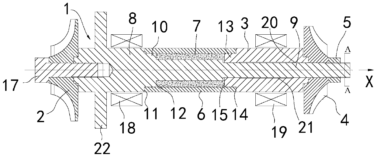
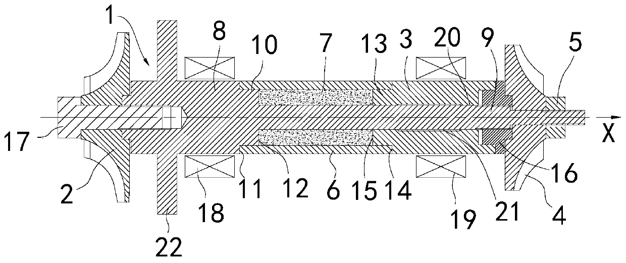
[0033] This part will describe the specific embodiment of the present invention in detail, and the preferred embodiment of the present invention is shown in the accompanying drawings. Each technical feature and overall technical solution of the invention, but it should not be understood as a limitation on the protection scope of the present invention.

[0034] In the present invention, if there is a description of directions (up, down, left, right, front and back), it is only for the convenience of describing the technical solution of the present invention, rather than indicating or implying that the referred technical features must have specific Orientation, construction and operation in a particular orientation, therefore should not be construed as limiting the invention.

[0035] In the present invention, the meaning of "several" is one or more, and the meaning of "multiple" is more than two. ", "within" and so on are understood as including the original number. In the de...


PUM


Abstract

The invention discloses a centrifugal type compressor shaft system structure. A main shaft, a first impeller, a second half shaft, a second impeller, a first locking part, a sleeve and a motor rotor are included; the main shaft comprises a first half shaft and a shaft core; the shaft core is connected with the first half shaft, and extends in the axial direction; the first impeller is connected with the first half shaft; the second half shaft is provided with a first shaft hole; the second impeller is provided with a second shaft hole, and the shaft core is sleeved with the second half shaft and the second impeller in sequence in the axial direction; the first locking part is arranged on the outer side of the second impeller in the axial direction, and the first locking part is connected with the shaft core to provide a locking force; the sleeve is arranged between the first half shaft and the second half shaft, and arranged on the shaft core in a sleeving manner, and an installing space is formed between the sleeve and the shaft core; and the motor rotor is arranged in the installing space. A centrifugal type compressor comprises the centrifugal type compressor shaft system structure. The locking part on the end portion is used for providing the axial locking force, so that the main shaft, the sleeve, the second half shaft and the second impeller are connected into a whole, the end face locking force can be used for remarkably improving the rigidity of a shaft system, and then the critical rotating speed of the shaft system is increased.

Description

technical field [0001] The invention is used in the field of compressors, and in particular relates to a shafting structure of a centrifugal compressor and the centrifugal compressor. Background technique [0002] In order to obtain high power density and performance, hydrogen fuel cells must work under relatively high gas pressure. Therefore, an air compressor with high efficiency and high compression ratio is required to provide high-pressure air for the fuel cell. At present, the compressors used in hydrogen fuel cells mainly include Roots type, scroll type, screw type and centrifugal type. Among them, the centrifugal compressor is usually directly driven by a high-speed motor. When the shaft system of the centrifugal compressor rotates at high speed, the rotor of the motor will generate a large centrifugal stress under the action of centrifugal force. In order to avoid damage caused by high-speed centrifugal stress, the diameter of the outer circle of the motor rotor ha...

Claims


Application Information

Patent Timeline
Patent Type & Authority Applications(China)
IPC IPC(8): F04D29/053F04D29/054F04D25/16
CPCF04D29/053F04D29/054F04D25/16
Inventor 熊万里张虎陈振宇薛建汤秀清
Owner GUANGZHOU HAOZHI ELECTROMECHANICAL
Why Eureka
Try Eureka