Expansion joint

An expansion joint, No. 1 technology, applied to expansion joints. It can solve problems such as difficulty in ensuring the tightness of casing expansion joints, excessive deformation of sealing materials, and inconvenient installation work, so as to achieve the effects of ensuring sealing performance, reducing wind resistance, and reducing leakage.

Active Publication Date: 2019-11-12
泰州市通力机械有限公司
View PDF8 Cites 3 Cited by
  • Summary
  • Abstract
  • Description
  • Claims
  • Application Information

AI Technical Summary

Problems solved by technology

[0004] The casing expansion joint is generally composed of two casings, and the two casings can slide. The sealing performance of the casing expansion joint is completely determined by the sealing material. The existing casing expansion joint only adopts a single sealing structure for sealing, while the thermal Water, steam, and oily media are easy to carry particulate impurities, and the impurities accumulate on the inner surface of the casing to agglomerate. When the expansion joint is telescopic, the agglomeration is likely to cause excessive deformation of the sealing material, resulting in leakage of hot water, steam, and oily media. , so it is difficult for a single sealing structure to guarantee the sealing performance of casing expansion joints. Moreover, the length of existing casing expansion joints is basically fixed. When connecting, it cannot be adjusted according to the actual length, which brings inconvenience to the installation work

Method used


Image

  • Expansion joint
  • Expansion joint
  • Expansion joint

Examples


Embodiment Construction

[0024] In order to make the technical means, creative features, goals and effects achieved by the present invention easy to understand, the present invention will be further described below in conjunction with specific embodiments.

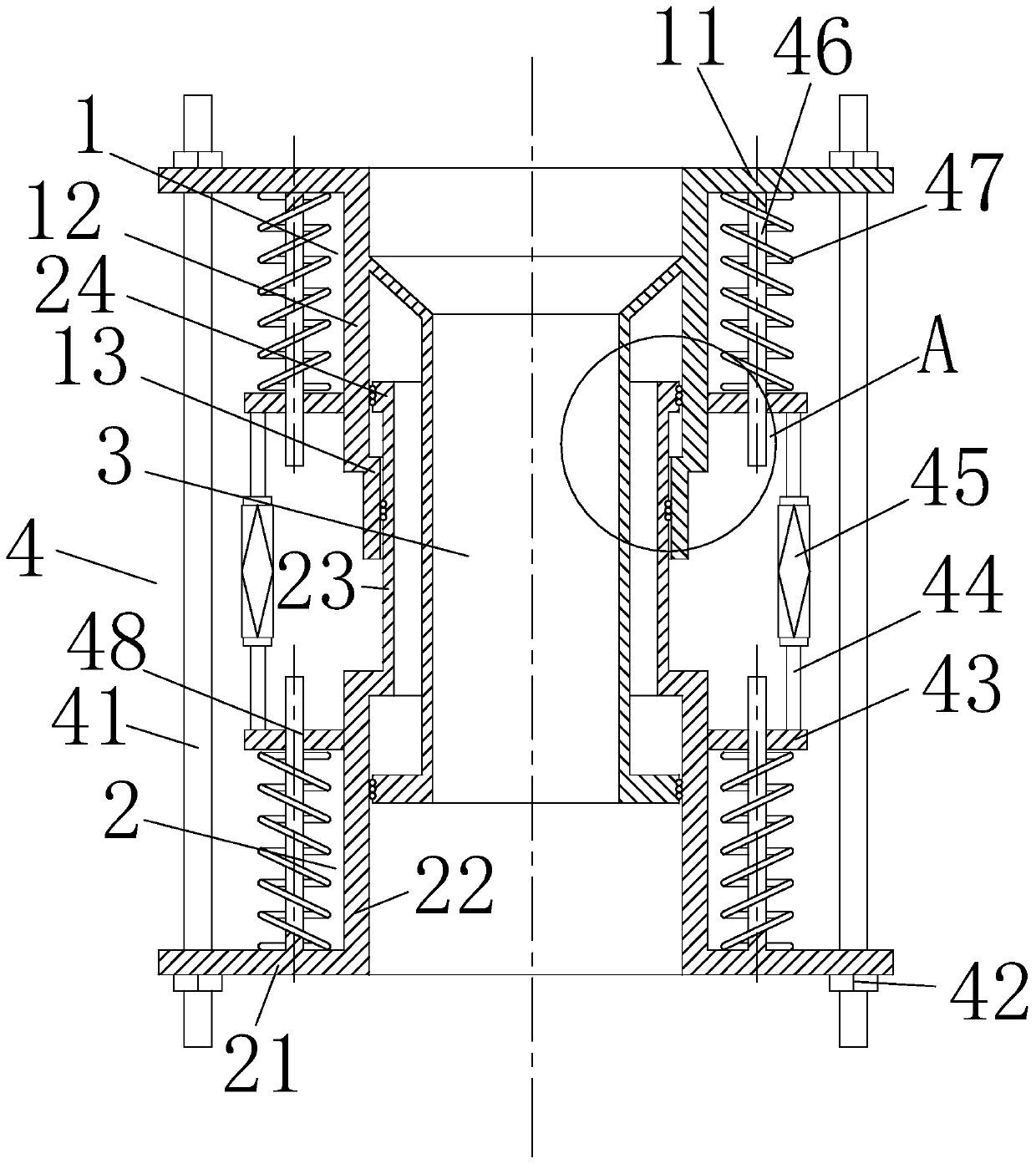
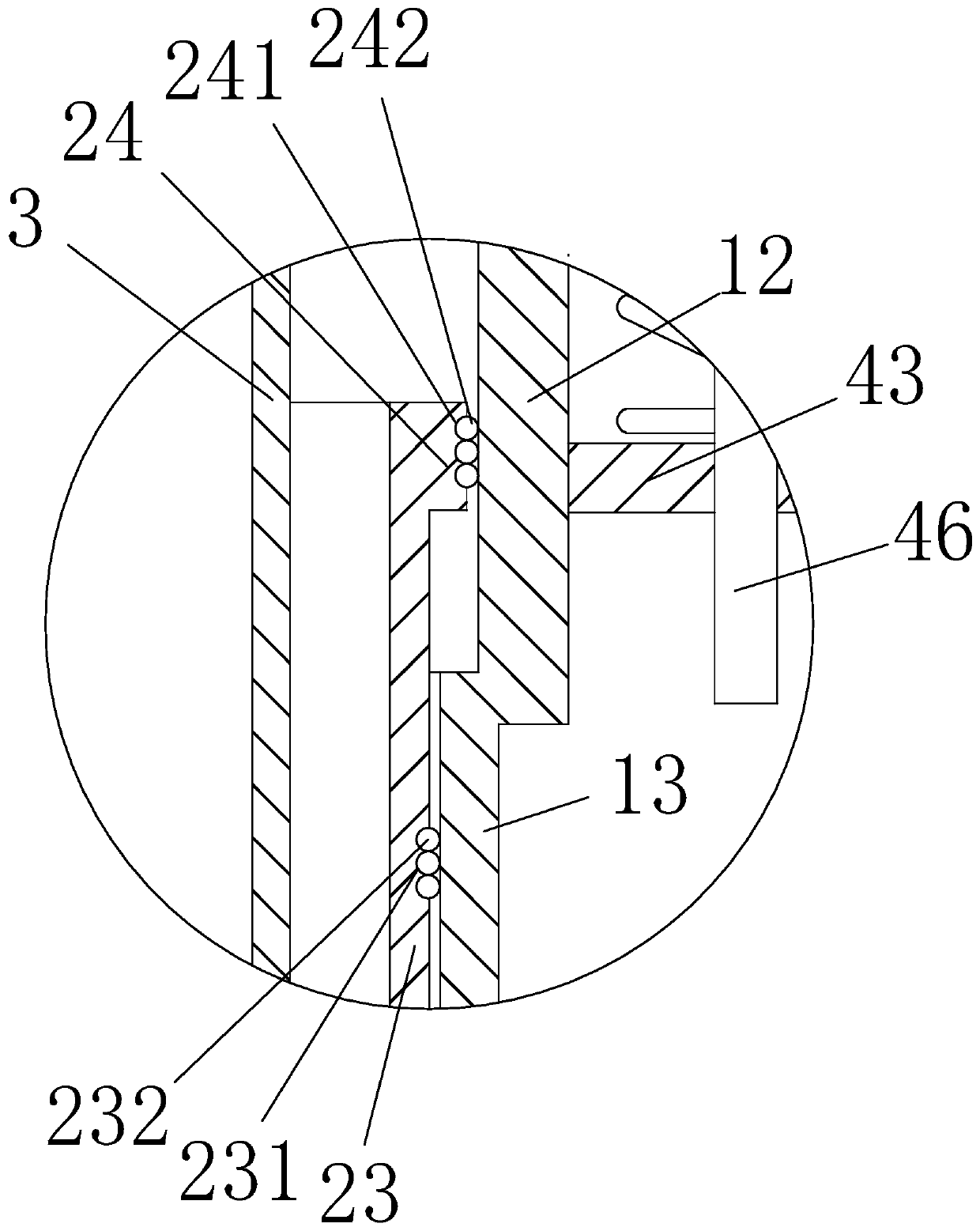
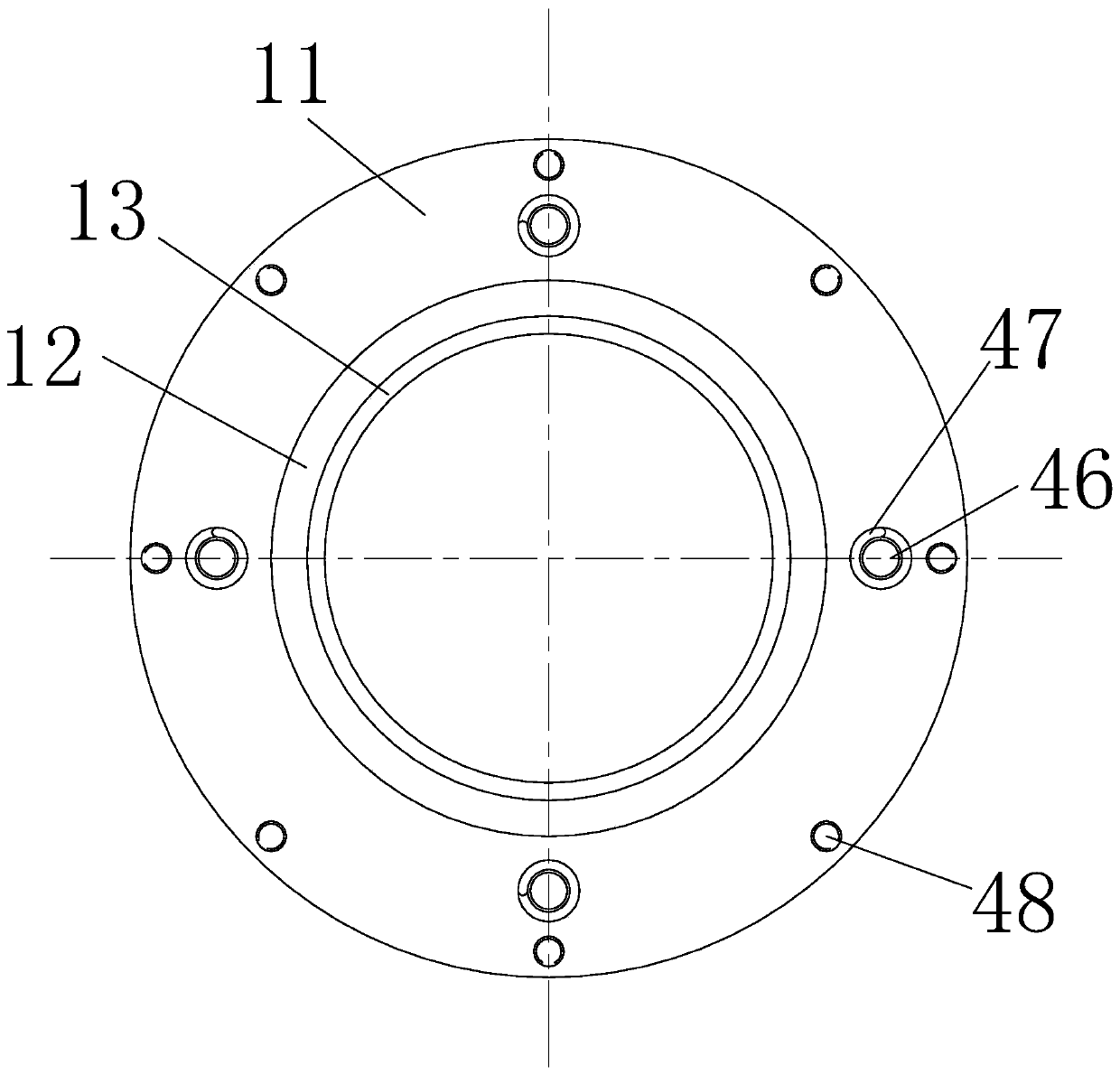
[0025] Such as Figure 1-Figure 5 As shown, an expansion joint according to the present invention includes a No. 1 end pipe 1, a No. 2 end pipe 2, an inner casing 3 and a sleeve connection structure 4. The No. 1 end pipe 1 is sleeved on the No. 2 end On the outside of the pipe 2, an inner casing 3 is arranged inside the second-end pipe 2, and one end of the inner casing 3 is connected to the first-end pipe 1, and the connection between the first-end pipe 1 and the second-end pipe 2 The space is connected by the sleeve connection structure 4, the distance between the first end pipe 1 and the second end pipe 2 is adjusted by the sleeve connection structure 4, and the elastic force of the expansion joint can be adjusted at the same time. The sealing...


PUM


Abstract

The invention relates to the technical field of pipeline accessories, and specifically relates to an expansion joint. The expansion joint comprises a first end pipe, a second end pipe, an inner sleevepipe and a sleeve connection structure, wherein the first end pipe is arranged at the outer side of the second end pipe in a sleeved manner; the inner sleeve pipe is arranged in the second end pipe;one end of the inner sleeve pipe is connected with the first end pipe; the first end pipe is connected with the second end pipe through the sleeve connection structure; the first end pipe comprises afirst connection plate, a first outer sleeve and a first extension sleeve; and the outer side of one end of the first outer sleeve is fixedly connected with the first connection plate. According to the expansion joint, through the arrangement for the inner sleeve pipe and three sealing rings, the first sealing ring is arranged between a second extension sleeve and the first extension sleeve, the second sealing ring is arranged between a first convex ring and a sleeve pipe main body, and the third sealing ring is arranged between a second convex ring and a second outer sleeve; and moreover, a wind-gathering cover is opposite to a fluid introduction direction, so that wind resistance is reduced.

Description

technical field [0001] The invention relates to the technical field of pipe fittings, in particular to an expansion joint. Background technique [0002] Expansion joints refer to flexible elements that can effectively compensate for axial deformation. For example, the expansion joints welded on the shell of a fixed tube-sheet heat exchanger have large axial flexibility and are easy to deform, which can compensate for the The thermal expansion difference caused by the different wall temperature reduces their axial load, thereby reducing the temperature difference stress of the tube, tube sheet and shell, and avoiding strength damage, instability damage and tube pull-off damage. [0003] The casing expansion joint is composed of inner and outer casings capable of axial relative movement, and the inner and outer casings are sealed with a stuffing box. When using, keep the pipes at both ends moving on the same axis. The product is mainly composed of sleeve (core pipe), shell, s...

Claims


Application Information

Patent Timeline
Patent Type & Authority Applications(China)
IPC IPC(8): F16L51/00
CPCF16L51/00
Inventor 不公告发明人
Owner 泰州市通力机械有限公司
Why Eureka
Try Eureka