A miniature measuring rake for wind tunnel test and its 3D printing method

A wind tunnel test and 3D printing technology, which is applied in measuring heat, measuring devices, and measuring fluid pressure, etc., can solve problems such as the contradiction between the number of measurement parameters and the degree of blockage, the limited space of the nozzle channel, and the large number of size constraints. Achieve the effect of improving the design space and application range, improving the freedom of mechanical design, and shortening the manufacturing time

Active Publication Date: 2022-07-29
BEIJING AERONAUTIC SCI & TECH RES INST OF COMAC +1
View PDF12 Cites 0 Cited by
  • Summary
  • Abstract
  • Description
  • Claims
  • Application Information

AI Technical Summary

Problems solved by technology

When carrying out the wind tunnel test with jet flow, it is necessary to measure the flow field parameters of the nozzle internal flow, and the space of the nozzle culvert flow channel is limited, which increases the requirement that the measuring rake accounts for no more than 6% of the blockage of the flow channel. Using the traditional Measuring rakes designed by mechanical processing have many size constraints, which will inevitably cause contradictions between the number of measurement parameters and the degree of clogging

Method used


Image

  • A miniature measuring rake for wind tunnel test and its 3D printing method
  • A miniature measuring rake for wind tunnel test and its 3D printing method
  • A miniature measuring rake for wind tunnel test and its 3D printing method

Examples


Embodiment Construction

[0052]In order to make the objectives, technical solutions and advantages of the present invention clearer, the present invention will be further described in detail below with reference to the embodiments and accompanying drawings. It should be understood that the specific embodiments described herein are only used to explain the present invention, but not to limit the present invention.

[0053] On the contrary, the present invention covers any alternatives, modifications, equivalent teaching methods and arrangements which are within the spirit and scope of the present invention as defined by the appended claims. Further, in order to give the public a better understanding of the present invention, some specific details are described in detail in the following detailed description of the present invention. The present invention can be fully understood by those skilled in the art without the description of these detailed parts.

[0054] It should be understood that the descri...


PUM


Abstract

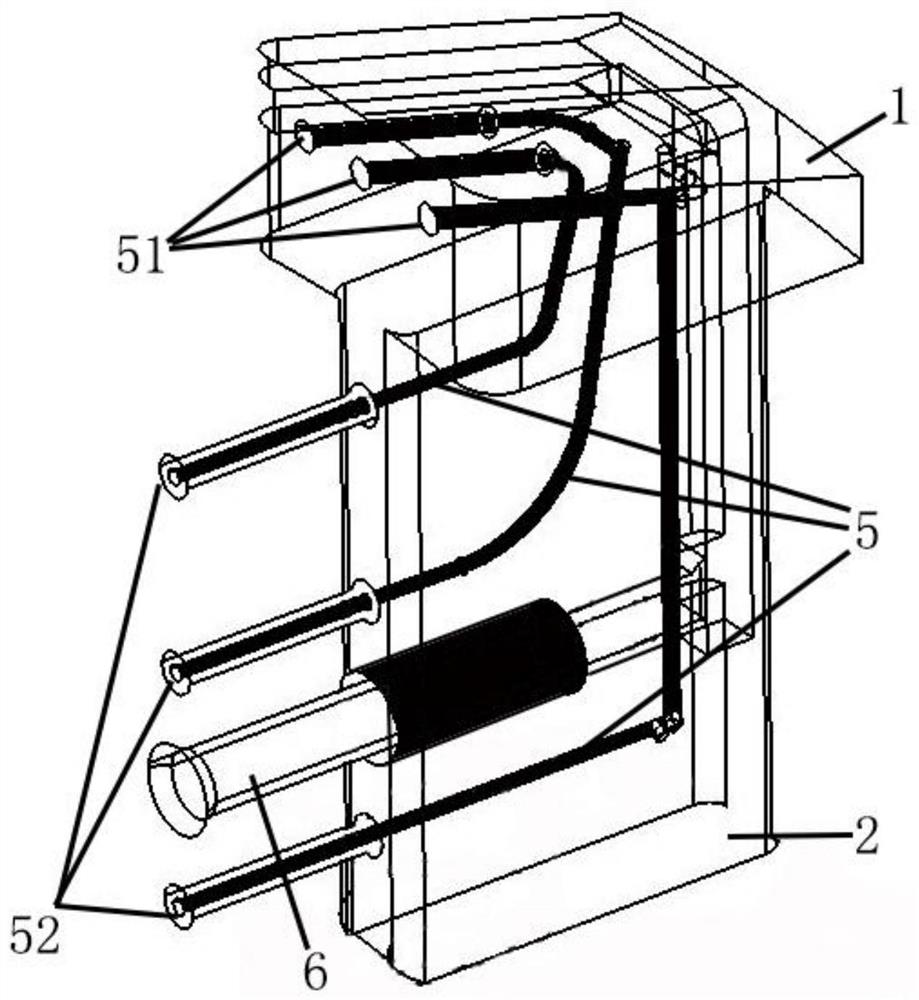
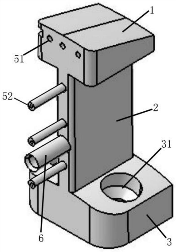
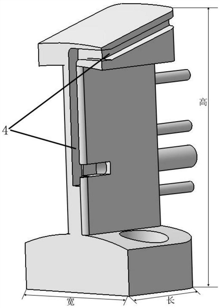
The invention belongs to the field of measuring rake manufacturing, and in particular relates to a miniature measuring rake used for wind tunnel test and a 3D printing method thereof. The measuring rake comprises: a measuring rake head, a measuring rake main body, a measuring rake base, a thermocouple wiring groove and a plurality of internal ventilation pipes; the measuring rake head, the measuring rake main body and the measuring rake base are connected in sequence; The internal ventilation pipe is arranged inside the measuring rake head and extends to the inside of the measuring rake body; the thermocouple wiring groove extends from the measuring rake head to the measuring rake body. Through 3D printing technology, the degree of freedom of mechanical design of the measuring rake can be improved, the size of the measuring rake can be effectively controlled, and the manufacturing time of the measuring rake can be shortened; the integration of thermocouples and pressure measuring tubes on the same measuring rake can realize the integrated acquisition of flow field parameters , reduce the number of measuring rakes, reduce the interference of measuring rakes on the flow field, and reduce the blockage of the flow channel on the premise of ensuring sufficient flow field information.

Description

technical field [0001] The invention belongs to the field of measuring rake manufacturing, and in particular relates to a miniature measuring rake used for wind tunnel test and a 3D printing method thereof. Background technique [0002] The measuring rake is an important device for collecting flow field parameter information in the wind tunnel test. In the wind tunnel test, the measuring rake is used to collect data such as pressure and temperature of the internal flow field or the external flow field. In the engine nacelle intake test, the pressure at the fan surface of the intake port needs to be measured with a measuring rake, to illustrate that the aerodynamic characteristics of the intake port can ensure uniform intake of the engine and meet the flow requirements under different working conditions; In the jet flow test, it is necessary to use a measuring rake to measure the pressure and temperature of a certain section of the nozzle to calculate whether the performance ...

Claims


Application Information

Patent Timeline
Patent Type & Authority Patents(China)
IPC IPC(8): G01M9/04G01K7/02G01L19/00B22F3/105B33Y10/00B33Y80/00
CPCG01M9/04G01K7/02G01L19/0007B33Y10/00B33Y80/00B22F10/00B22F12/90B22F10/28Y02P10/25
Inventor 闫海津赖国俊杜玺邓志林大楷巴玉龙
Owner BEIJING AERONAUTIC SCI & TECH RES INST OF COMAC
Why Eureka
Try Eureka