Pollution source coagulable particulate matter sampling device and method

A sampling device and particle technology, applied in the field of testing, can solve the problems of different graded particles, the same cutting point, accurate measurement of condensable particles, etc., and achieve the effect of reducing measurement errors

Active Publication Date: 2019-11-12
TSINGHUA UNIV
View PDF6 Cites 2 Cited by
  • Summary
  • Abstract
  • Description
  • Claims
  • Application Information

AI Technical Summary

Problems solved by technology

The sum of the two is the concentration of condensable particulate matter. The disadvantage of the method is that water vapor is also condensed out during the process of flue gas condensation and cooling, and some SO soluble in water in the flue gas 2 gases, soluble in condensed water, thus giving a positive bias to accurate measurements of condensable particulate matter
There are two cyclones in the unit to remove specific particulate matter from the flue gas, which will cause measurement errors
On the one hand, the cutting points of the two cyclone cutters cannot be exactly the same, resulting in different classified particles
The flue gas flow rate of the two channels cannot be exactly the same, which will also cause the cutting point of the cyclone cutter to be different, resulting in measurement errors; on the other hand, the two cyclone classifiers need to be heated and kept warm, and at the same time increase the complexity of the sampling system, thus affecting the sampling System Portability

Method used


Image

  • Pollution source coagulable particulate matter sampling device and method
  • Pollution source coagulable particulate matter sampling device and method

Examples


Embodiment Construction

[0030] The present invention will be further described in detail below in conjunction with the drawings.

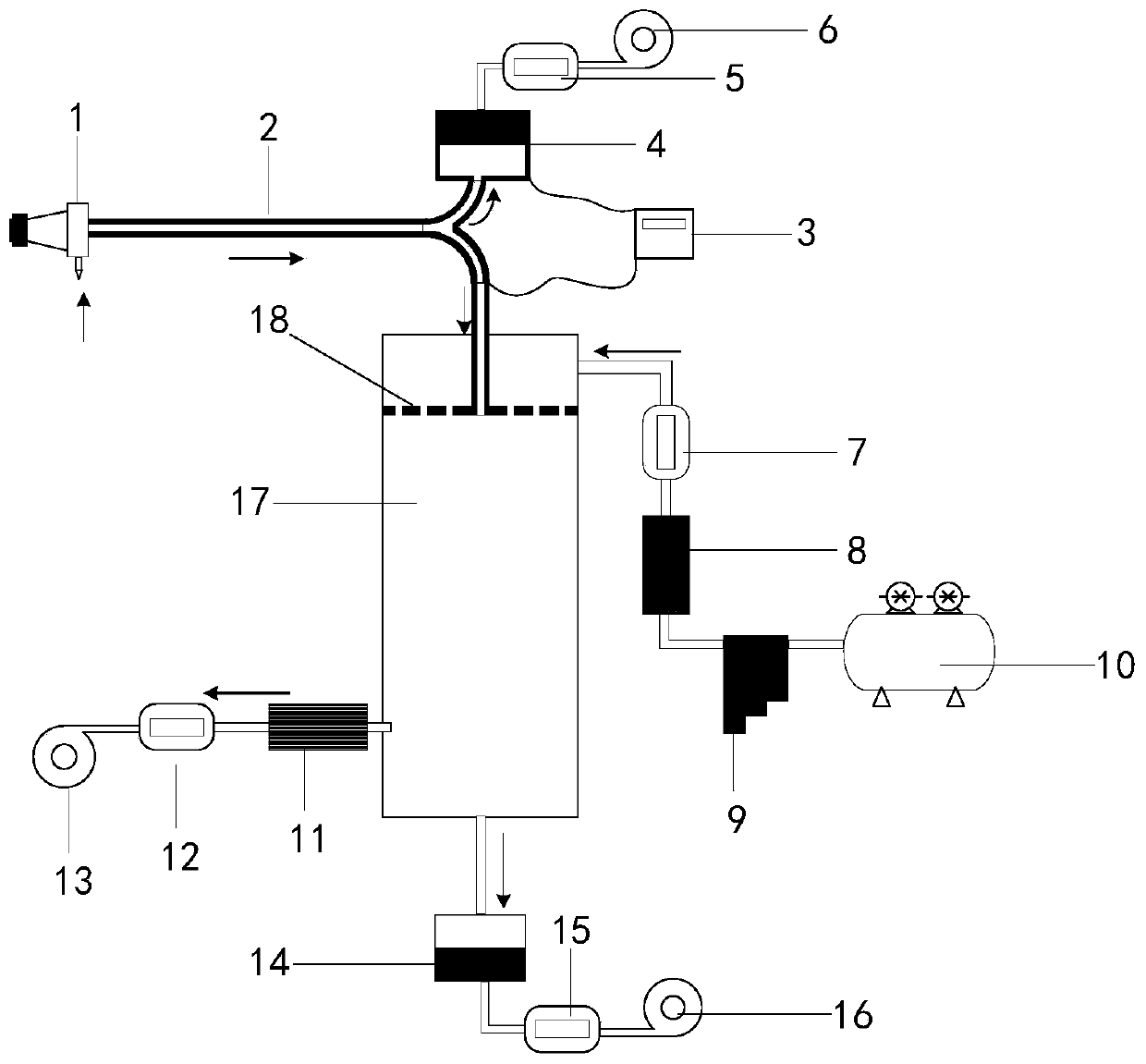
[0031] Such as figure 1 The illustrated embodiment of the present invention includes: particulate classification device 1, flue gas pipeline 2, heating and heat preservation device 3, filterable particulate matter collection device 4, filterable particulate matter flow meter 5, filterable particulate matter extraction device 6, dilution air Flow meter 7, dilution air particulate filter device 8, dilution air organic matter and water vapor removal device 9, dilution air supply device 10, bypass air particulate filter device 11, bypass air flow meter 12, bypass air extraction device 13, The total particulate matter collection device 14, the total particulate matter flow meter 15, the total particulate matter extraction device 16, the dilution chamber 17 and the air distribution plate 18; wherein the particulate matter classification device 1 is connected to the air distribution...


PUM

PropertyMeasurementUnit
particle diameteraaaaaaaaaa

Abstract

The invention discloses a pollution source coagulable particulate matter sampling device and method in the field of pollution source monitoring. A particulate matter classification device is placed ina fixed pollution source flue and is connected with each of an air distribution plate in a dilution cavity and a filterable particulate matter collection device through flue gas pipelines; a diluentair supply device, a diluent air organic matter and water vapor removal device, a diluent air particulate matter filtering device, a diluent air flow meter and a diluent air inlet of the dilution cavity are connected in sequence through a pipeline; a fist mixed gas outlet of the dilution cavity, a bypass gas particulate matter filtering device, a bypass gas flow meter and a bypass gas extraction device are connected in sequence through a pipeline; and a second mixed gas outlet of the dilution cavity, a total particulate matter collection device, a total particulate matter flow meter and a total particulate matter air extractor are connected in sequence through a pipeline. According to a measurement method provided by the invention, the particulate matter and total particulate matters can be collected at the same time, and then a difference value is calculated to obtain the coagulable particulate matters.

Description

Technical field [0001] The invention belongs to the technical field of testing, and specifically relates to a sampling device and a sampling method for condensable particulate matter from a pollution source. Background technique [0002] The particulate matter emitted by stationary pollution sources not only includes filterable particulate matter that exists in the flue as liquid or solid particles, but also includes condensable particles that are gaseous at flue temperature and are discharged from the flue into the atmosphere in a short time and condense into solid or liquid particles. particulates. [0003] At present, the most commonly used sampling device and method for condensable particulate matter from fixed pollution sources is the United States Environmental Protection Agency standard method (United States Environmental Protection Agency method device 202), in the United States Environmental Protection Agency (USEPA). Method 202-Dry impinger method for determining The dev...

Claims


Application Information

Patent Timeline
Patent Type & Authority Applications(China)
IPC IPC(8): G01N1/24G01N1/34G01N5/02
CPCG01N1/2273G01N1/24G01N1/34G01N5/02
Inventor 蒋靖坤邓建国王刚张莹李妍菁
Owner TSINGHUA UNIV
Why Eureka
Try Eureka