Refrigerant radiating device, air conditioner installed therein, and temperature control method

A temperature control method and refrigerant heat dissipation technology, which are applied in the field of temperature control of refrigerant heat dissipation devices and refrigerant radiators, can solve the problems of inverter condensation, damage to inverters, and insignificant heat dissipation effect, so as to improve full-load working capacity, The effect of ensuring the working temperature and reducing the energy loss

Active Publication Date: 2018-04-27
HAIER GRP CORP +1
View PDF6 Cites 0 Cited by
  • Summary
  • Abstract
  • Description
  • Claims
  • Application Information

AI Technical Summary

Problems solved by technology

[0005] This patent uses the refrigerant to dissipate heat from the inverter, which can improve the working capacity of the air conditioner. However, since the flow of the refrigerant cannot be controlled in this patent, if the air conditioning system uses the refrigerant on the low-pressure side for heat dissipation, condensation will occur on the outer surface of the inverter. Exposure phenomenon, affecting the normal operation of the inverter, or even destroying the inverter
If the air conditioning system uses the refrigerant on the high-voltage side for heat dissipation, the heat dissipation effect is not obvious, and the inverter still cannot work at full load when the outdoor temperature is high

Method used


Image

  • Refrigerant radiating device, air conditioner installed therein, and temperature control method
  • Refrigerant radiating device, air conditioner installed therein, and temperature control method

Examples


Embodiment 1

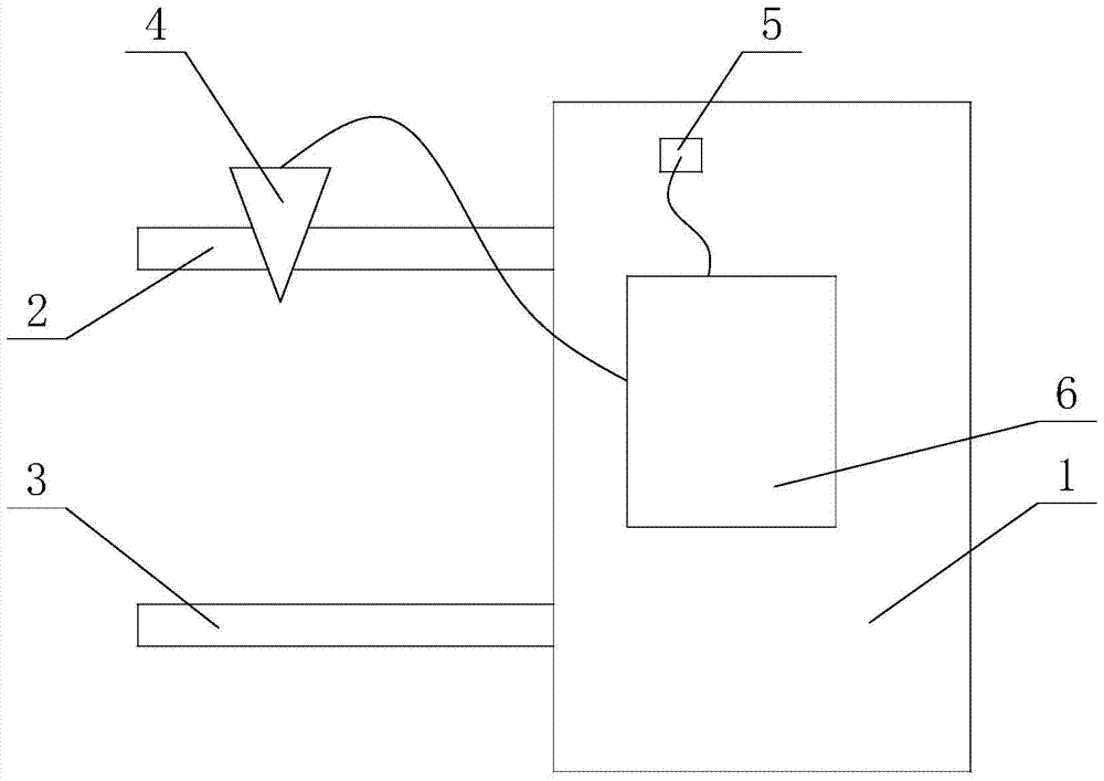
[0031] Such as figure 1 Shown is a structural diagram of the cooling medium cooling device provided in the first embodiment.

[0032] A refrigerant cooling device provided in this embodiment includes a controller, a radiator 1 , a refrigerant inlet pipe 2 , a refrigerant outlet pipe 3 , an expansion valve 4 and a temperature sensor 5 . Both the refrigerant inlet pipe 2 and the refrigerant outlet pipe 3 are connected to the radiator 1 , the expansion valve 4 is arranged on the pipeline of the refrigerant inlet pipe 2 , and the temperature sensor 5 is attached to the outer surface of the radiator 1 .

[0033] The expansion valve 4 and the temperature sensor 5 are connected to the controller, and the controller is used to receive the detection signal of the temperature sensor 5 to adjust the opening of the expansion valve 4 and realize the constant temperature control of the radiator 1 . If the radiator 1 is installed on the frequency converter, the constant temperature control ...

Embodiment 2

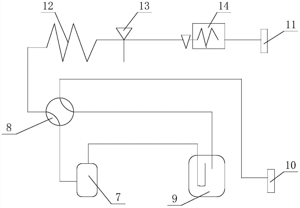
[0036] Such as figure 2 Shown is the structural diagram of the air conditioner provided in the second embodiment.

[0037] The air conditioner installed with the refrigerant heat exchange device in Embodiment 1 provided in this embodiment includes a frequency converter, a compressor 7, a four-way valve 8, a gas-liquid separator 9, a gas refrigerant pipe 10, a liquid refrigerant pipe 11, Outdoor heat exchanger 12, throttle valve 13, cooler 14 and other components.

[0038] The gaseous refrigerant pipe 10 is connected to the first valve port of the four-way valve 8 , and the liquid refrigerant pipe 11 is connected to the second valve port of the four-way valve 8 . The refrigerant inlet and refrigerant outlet of the compressor 7 are respectively connected to the third valve port of the four-way valve 8 and the gas-liquid separator 9 . The third valve port of the four-way valve is connected with the gas-liquid separator 9 .

[0039] Further, an outdoor heat exchanger 12 , a th...

Embodiment 3

[0042] A method for controlling the temperature of the refrigerant cooling device in Embodiment 1 is implemented according to the following steps:

[0043] Step S00: preset the target temperature value T in the internal memory of the controller m and the limit temperature value T a . Among them, the target temperature value T m It means to control the temperature of the inverter at a fixed value during actual operation to ensure that the inverter does not condense or overheat. It can also be considered that this value is the optimum operating temperature value of the inverter.

[0044] Limit temperature T a It means that when the environmental stability is lower than a certain value, there is no need to use a refrigerant cooling device at this time, and the inverter will not overheat.

[0045] Step S10: the temperature sensor 5 detects the temperature signal on the surface of the radiator 1, and transmits the temperature signal to the controller to obtain the detected tem...


PUM


Abstract

The invention discloses a refrigerant heat dissipation device, which belongs to the field of frequency conversion air conditioners. The refrigerant heat dissipation device includes a controller, a radiator, a refrigerant inlet pipe and a refrigerant outlet pipe connected with the radiator, and the refrigerant inlet pipe is provided with a An expansion valve, a temperature sensor is pasted on the radiator, and the expansion valve and the temperature sensor are connected with the controller. An air conditioner equipped with a refrigerant heat exchange device includes a frequency converter, an IPM drive belt is provided on the frequency converter, and one side of the radiator is in contact with the IPM drive belt. The refrigerant heat dissipation device provided by the present invention enables the frequency converter to operate at a set optimal working temperature for a long time, thereby ensuring that the frequency converter will not be overheated or condensed, and can work at full load for a long time.

Description

technical field [0001] The invention relates to the field of frequency conversion air conditioners, in particular to a refrigerant radiator device, an air conditioner equipped with a refrigerant radiator device, and a method for controlling the temperature of the refrigerant radiator. Background technique [0002] IPM (Intelligent Power Module), that is, intelligent power module, not only integrates power switching devices and driving circuits, but also integrates fault detection circuits such as overvoltage, overcurrent and overheating. [0003] Inverter air conditioners are becoming more and more popular due to their low energy consumption. Inverter air conditioners usually require a frequency converter to control the speed of the compressor. The higher the frequency of the frequency converter, the greater the heat generated by the frequency converter. Therefore, when the outdoor temperature is high, it is difficult for the frequency converter to effectively dissipate heat...

Claims


Application Information

Patent Timeline
Patent Type & Authority Patents(China)
IPC IPC(8): F24F11/33F24F11/84H02M1/00F24F140/20
CPCF24F13/30F24F11/30F24F11/83F24F11/84F24F2110/00H02M1/0048Y02B70/10
Inventor 王锋侯庆渠张锐刚程绍江赵永俊时斌刘宝秦楠杜荣辉张万英
Owner HAIER GRP CORP
Why Eureka
Try Eureka