Eureka AIR delivers breakthrough ideas for toughest innovation challenges, trusted by R&D personnel around the world.

Optical regulation and control element and display device

An optical control and display device technology, applied in optics, nonlinear optics, instruments, etc., can solve the problems of poor overall light use efficiency and decreased brightness, and achieve the effect of avoiding light leakage from large viewing angles

Inactive Publication Date: 2019-11-12
AU OPTRONICS CORP
View PDF8 Cites 0 Cited by
  • Summary
  • Abstract
  • Description
  • Claims
  • Application Information

AI Technical Summary

Problems solved by technology

However, disposing a shading element with a black light-absorbing material will also cause a large decrease in brightness in the front view direction, resulting in poor overall light use efficiency

Method used


Image

  • Optical regulation and control element and display device
  • Optical regulation and control element and display device
  • Optical regulation and control element and display device

Examples


Embodiment Construction

[0015] In the drawings described below, the thickness of layers, films, panels, regions, etc., are exaggerated for clarity. Throughout the specification, the same reference numerals denote the same elements. It will be understood that when an element such as a layer, film, region, or substrate is referred to as being "on" or "connected to" another element, it can be directly on or connected to the other element, or Intermediate elements may also be present. In contrast, when an element is referred to as being "directly on" or "directly connected to" another element, there are no intervening elements present. As used herein, "connected" may refer to physical and / or electrical connection. Furthermore, "electrically connected" or "coupled" means that other elements may exist between two elements.

[0016] It should be understood that although the terms "first", "second", "third" etc. may be used herein to describe various elements, components, regions, layers and / or sections, ...


PUM


Abstract

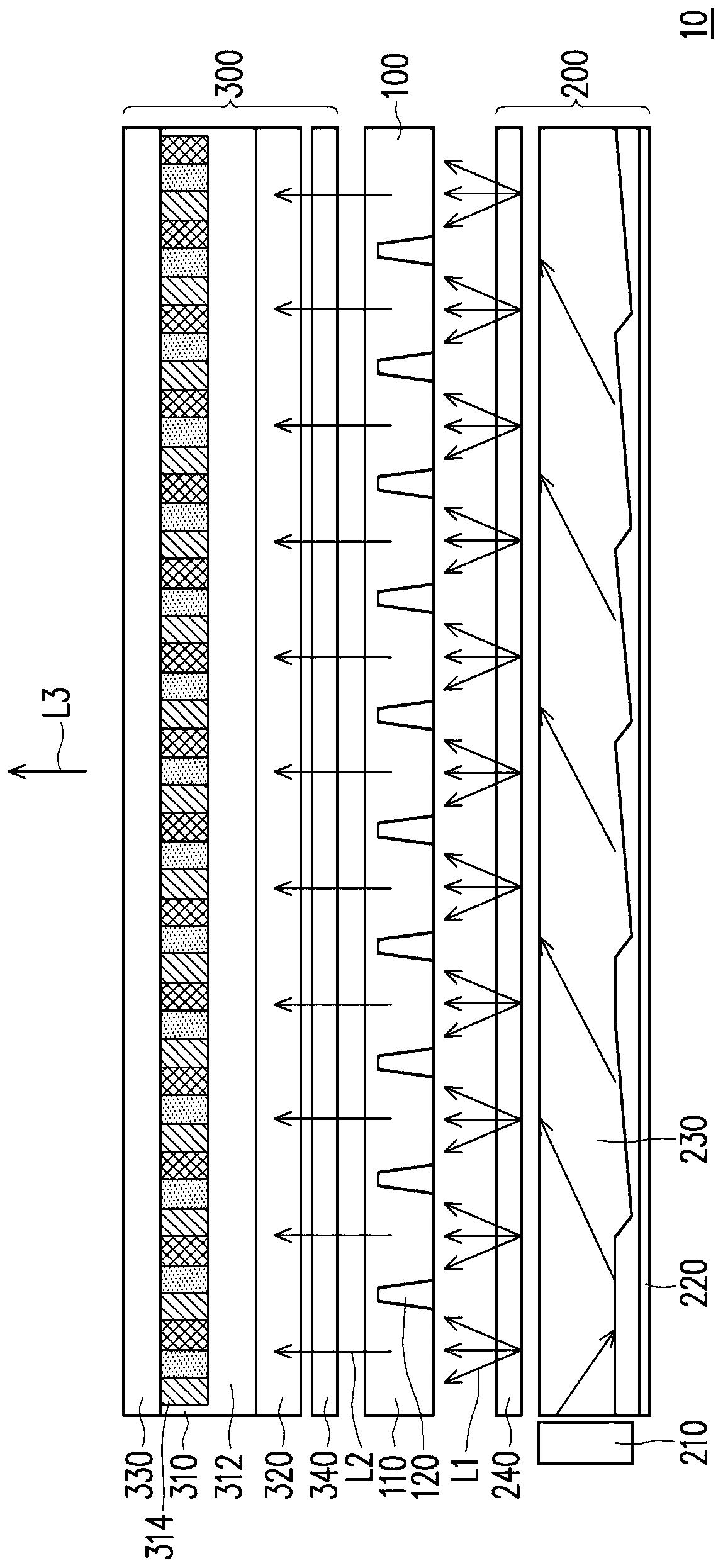
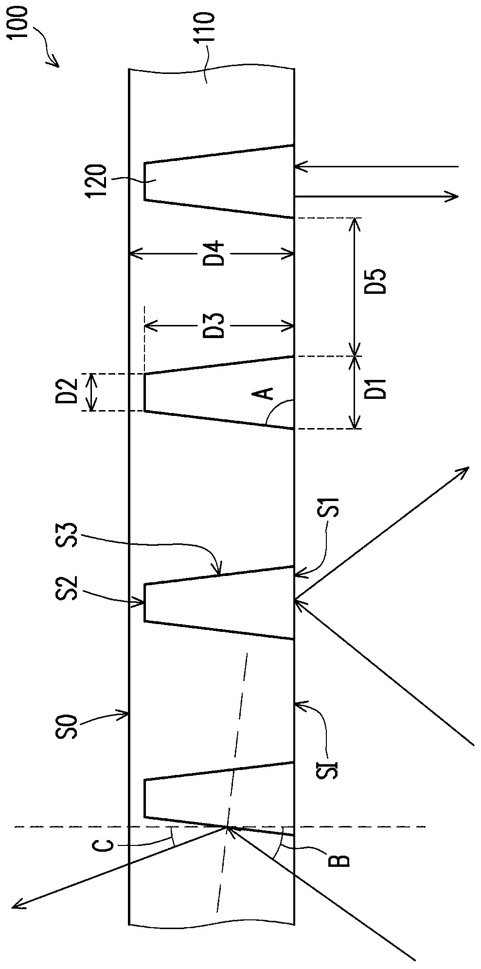
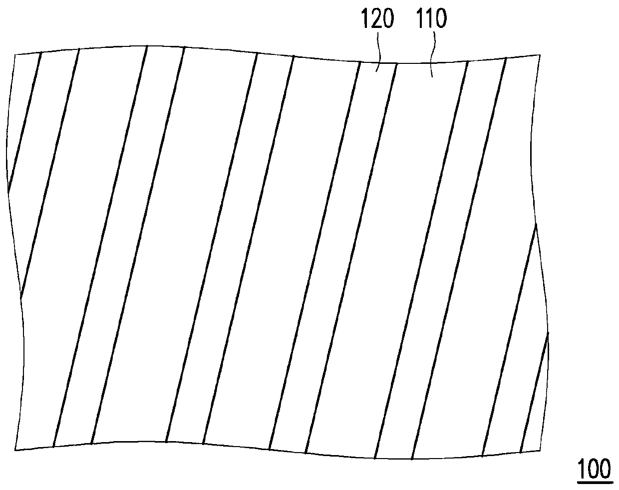
The invention provides an optical regulation and control element and a display device. The optical regulation and control element is suitable for allowing a light beam to pass through and comprises alight-transmitting substrate and a plurality of reflection structures. The light-transmitting substrate is provided with a light-in surface and a light-out surface which are opposite to each other. The reflection structures are arranged in the light-transmitting substrate, each reflection structure is provided with a bottom face adjacent to the light-in face and a side face connected to the bottomface, and the width of each reflection structure in the direction of the horizontal view angle is decreased progressively from the end adjacent to the light-in face to the end away from the light-inface. The bottom surface and the side surface are respectively adapted to reflect a part of the light beam, and in a direction perpendicular to the bottom surface, a transmission direction of the partof the light beam reflected by the bottom surface and a transmission direction of the part of the light beam reflected by the side surface are opposite to each other.

Description

technical field [0001] The present invention relates to an optical element and an electronic device, and in particular to an optical control element and a display device. Background technique [0002] In the current liquid crystal display using a backlight module, once the liquid crystal display is turned on, the backlight module will be turned on all the time and provide backlight. Therefore, when a picture is displayed, the display medium containing the liquid crystal material in the liquid crystal display is used to turn on or off the backlight provided by the backlight module to allow the backlight to pass or not pass through. However, when the liquid crystal display is displayed in a dark state (that is, the display medium containing the liquid crystal material closes the backlight provided by the backlight module so that the backlight does not pass through), the display medium containing the liquid crystal material cannot completely shield the display surface that is v...

Claims


Application Information

Patent Timeline
Patent Type & Authority Applications(China)
IPC IPC(8): G02F1/13357
CPCG02F1/133605G02F1/133524G02F1/133567G02F1/1323G02F1/133553G02F1/1347G02F1/13478
Inventor 李欣浤詹钧翔范铎正蔡庭玮江启圣蔡旻锦
Owner AU OPTRONICS CORP
Why Eureka
Eureka Blog
Learn More