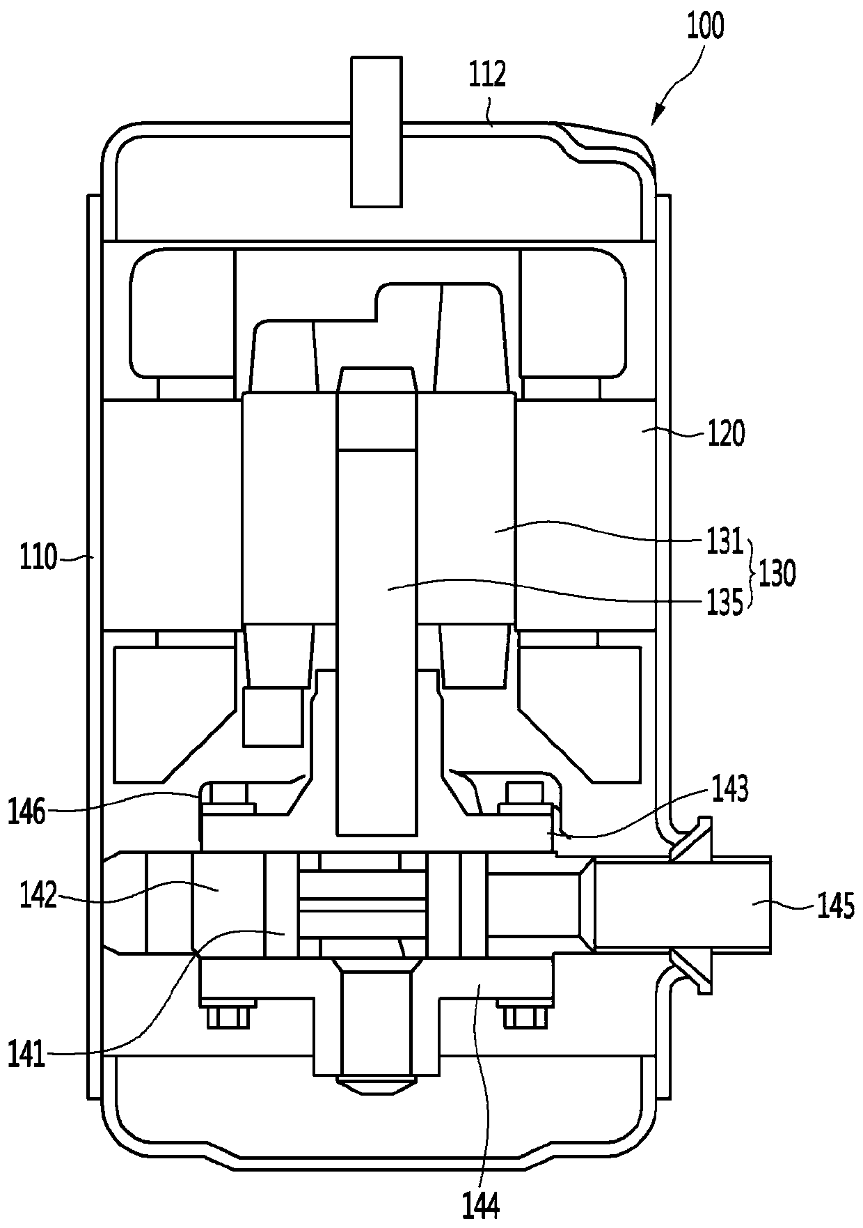
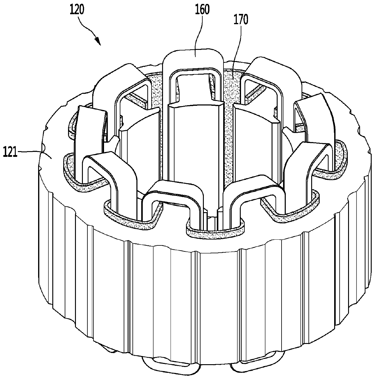
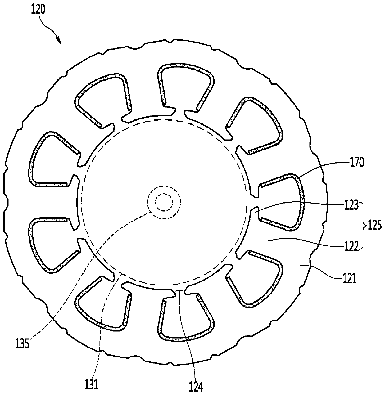
Stator for compressor motor
A technology for compressors and stators, applied in mechanical equipment, electromechanical devices, machines/engines, etc., can solve problems such as reduced compressor motor drive efficiency and difficulty in reducing electromagnetic noise, and achieve the goals of suppressing vibration, reducing electromagnetic noise, and reducing costs Effect
- Summary
- Abstract
- Description
- Claims
- Application Information
AI Technical Summary
Problems solved by technology
Method used
Image

Examples
Embodiment Construction
[0026] Hereinafter, some embodiments of the present invention will be described in detail through exemplary drawings. Components in each drawing are assigned reference signs, and even if the same component is shown in different drawings, it should be noted that the same reference signs are used as much as possible. In addition, in describing the embodiments of the present invention, when it is judged that the detailed description of related known configurations or functions hinders the understanding of the embodiments of the present invention, the detailed description will be omitted.
[0027] Also, terms such as first, second, A, B, a, b, etc. may be used in describing the constituent elements of the embodiments of the present invention. Such terms are used only to distinguish the constituent elements from other constituent elements, and the nature or sequence or sequence of the related constituent elements will not be used for these. When it is described that a constituent ...
PUM
 Abstract
Description
Claims
Application Information
PatSnap Eureka turns technology decisions into work you can execute. Powered by our Innovation Knowledge Graph, it runs expert workflows across engineering, life sciences, materials and intellectual property. Get your review-ready output in minutes.


