Control circuit for controlling power transistor, driving circuit, LED lamp system and control method

A technology of power transistors and control circuits, applied in the field of control circuits, can solve problems such as low efficiency of LED drive circuits, influence of LED circuit control accuracy, and inability to perform precise regulation.

Pending Publication Date: 2019-11-12
杭州必易微电子有限公司
View PDF0 Cites 3 Cited by
  • Summary
  • Abstract
  • Description
  • Claims
  • Application Information

AI Technical Summary

Problems solved by technology

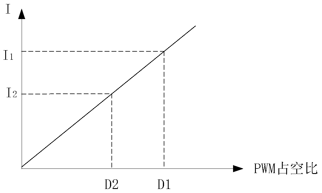
When the duty cycle D2 is further reduced, the control accuracy of the LED circuit is affected due to the bias at the input terminal of the operational amplifier.
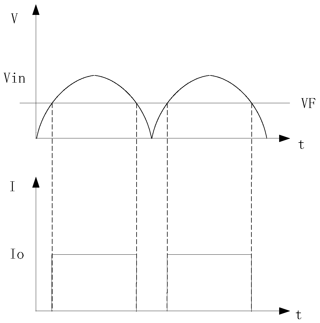
[0003] image 3 It is a schematic diagram of part of the signal waveform of the existing linear LED drive circuit; image 3 It can be seen that the loss flowing through the transistor Q is (Vin-VF)*Io, the loss of the tr

Method used


Image

  • Control circuit for controlling power transistor, driving circuit, LED lamp system and control method
  • Control circuit for controlling power transistor, driving circuit, LED lamp system and control method
  • Control circuit for controlling power transistor, driving circuit, LED lamp system and control method

Examples


Embodiment Construction

[0088]Preferred embodiments of the present invention will be described in detail below in conjunction with the accompanying drawings.

[0089] In order to further understand the present invention, the preferred embodiments of the present invention are described below in conjunction with examples, but it should be understood that these descriptions are only to further illustrate the features and advantages of the present invention, rather than limiting the claims of the present invention.

[0090] The description in this part is only for several typical embodiments, and the present invention is not limited to the scope of the description of the embodiments. The mutual replacement of the same or similar prior art means and some technical features in the embodiments is also within the scope of the description and protection of the present invention.

[0091] "Coupling" or connection in the specification includes both direct connection and indirect connection, such as connection t...


PUM


Abstract

The invention discloses a control circuit for controlling a power transistor, a driving circuit, an LED lamp system and a control method. The control circuit receives an adjusting signal, and the control circuit is used for adjusting the amplitude of a current flowing through the power transistor based on the adjusting signal when a characterization value of the adjusting signal is greater than afirst threshold value; the control circuit is used for adjusting the current flowing time of the power transistor based on the adjusting signal when the characterization value of the adjusting signalis less than a second threshold value, wherein the second threshold is less than or equal to the first threshold. According to the invention, the control precision and efficiency can be improved. Whenthe characterization value (such as the duty ratio) of the adjusting signal (such as the PWM signal) is a smaller value, the control precision is improved; meanwhile, the drive circuit is small in loss and high in efficiency. The invention is applied to an LED drive scheme, so the dimming precision of an LED drive circuit is improved.

Description

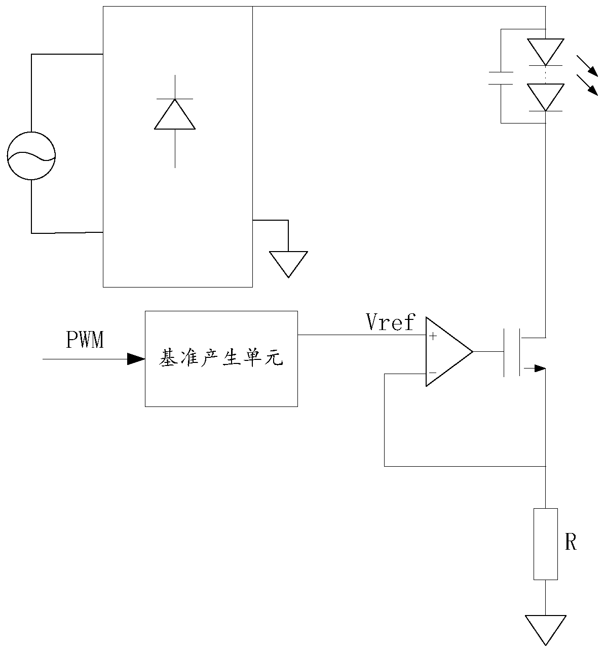
technical field [0001] The invention belongs to the technical field of control circuits, and in particular relates to a control circuit, a drive circuit, an LED lamp system and a control method for controlling a power transistor. Background technique [0002] The linear LED driving circuit is gradually accepted by the market due to its simple and convenient design, but there are problems in the prior art. figure 1 It is a circuit schematic diagram of an existing linear LED driving circuit, figure 2 It is a schematic diagram of the relationship between the duty cycle and Io in the existing linear LED drive circuit; please refer to figure 1 , figure 2 In the prior art, a PWM control reference generating unit is used to generate Vref, the sampling voltage and Vref are obtained through an operational amplifier, and a control signal is output to control the current flowing through the transistor Q, thereby realizing dimming of the LED driving circuit. Adjust the current flow...

Claims


Application Information

Patent Timeline
IPC IPC(8): H05B33/08H05B44/00
CPCH05B45/20H05B45/325H05B45/10H05B45/395Y02B20/30H03K17/687
Inventor 张波
Owner 杭州必易微电子有限公司
Why Eureka
Try Eureka