Pulping system for improving slurry concentration uniformity

A technology of slurry concentration and uniformity, applied in mixers, mixers, mixing methods and other directions with rotary stirring devices, it can solve the problems of uneven slurry, high slurry concentration, low beating, etc., and achieve work efficiency. The effect of high, uniform mixing of slurry and saving power source

Inactive Publication Date: 2019-11-15
长兴东锦纺织品有限公司
View PDF1 Cites 6 Cited by
  • Summary
  • Abstract
  • Description
  • Claims
  • Application Information

AI Technical Summary

Problems solved by technology

[0004] The purpose of the present invention is to address the deficiencies of the prior art, provide power through the drive device to synchronously drive the control part and the pulp return assembly to work, and then cooperate with the control part, the pulp return assembly and the filter assembly to realize the pulping process. The high-concentration slurry deposited at the bottom of the beating barrel is transported to the feed port of the beating barrel to mix with the low-concentration slurry and beating, and the high-concentration slurry at the bottom of the beating barrel is stirred by the filter assembly, which solves the problem of The high-concentration slurry sinks to the bottom, resulting in a high concentration of slurry at the bottom of the equipment and a low concentration of slurry at the upper end of the equipment, resulting in uneven beating and the inability to stir the slurry at the bottom of the equipment. The control structure of the equipment is simple to operate Convenience and a common drive greatly reduces energy consumption and improves work efficiency

Method used


Image

  • Pulping system for improving slurry concentration uniformity
  • Pulping system for improving slurry concentration uniformity
  • Pulping system for improving slurry concentration uniformity

Examples


Embodiment 1

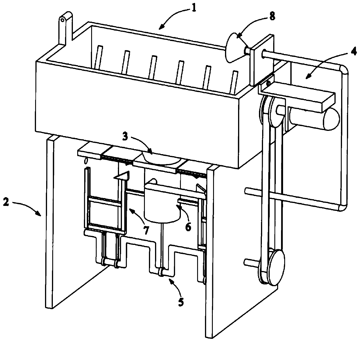
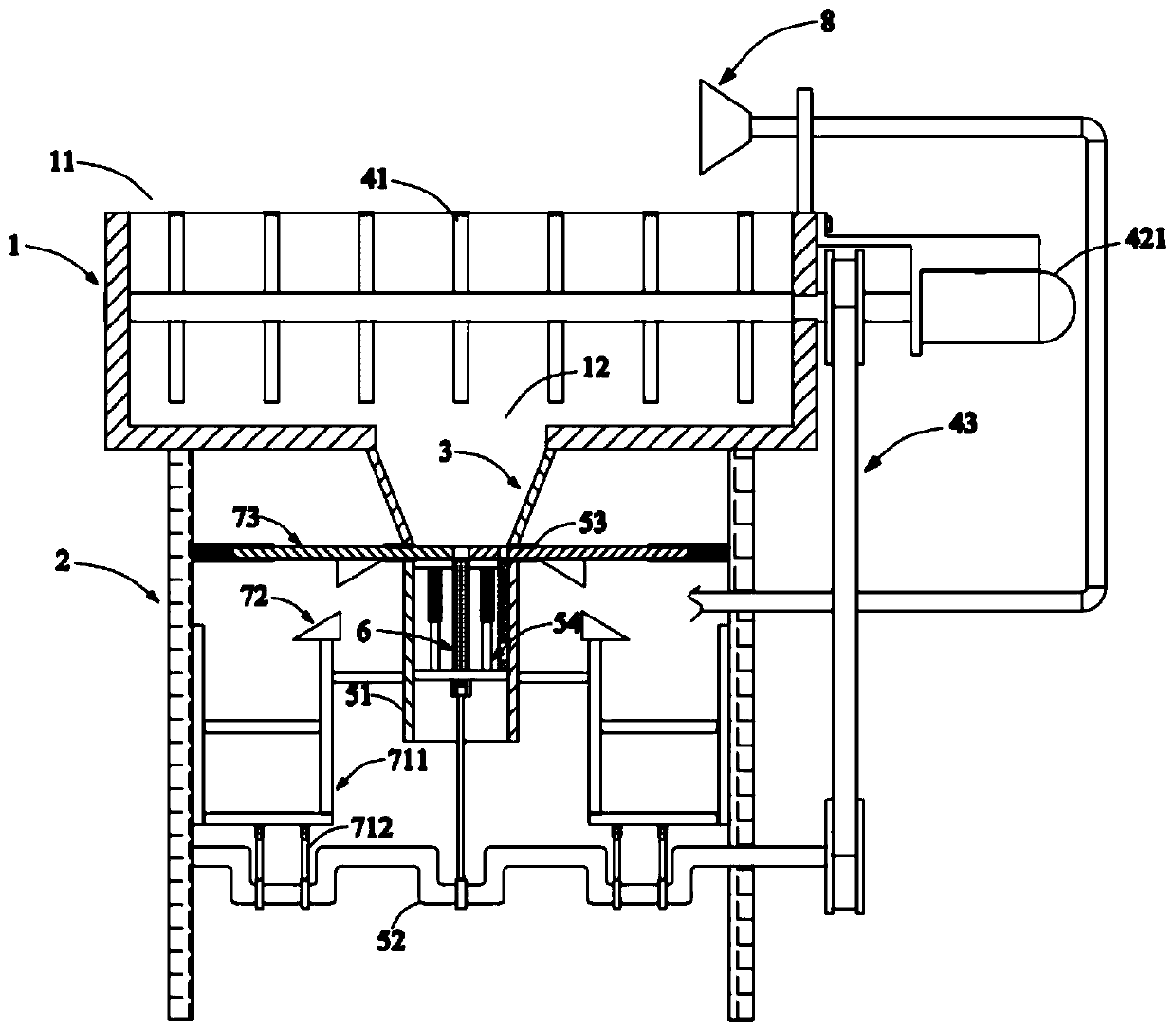
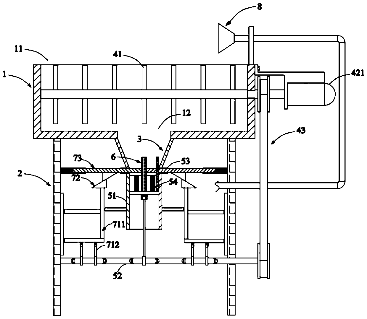
[0051] Such as Figure 1 to Figure 18 As shown, a beating system that improves the uniformity of slurry concentration includes:

[0052] A beating bucket 1, the beating bucket 1 is installed on the support plate 2, the top of the beating bucket 1 is provided with a feed port 11 and the bottom is provided with a material leakage port 12, and a funnel 3 is provided below the material leakage port 12;

[0053] Stirring assembly 4, described stirring assembly 4 comprises the stirring paddle 41 installed in beating barrel 1, the driving device 42 that is arranged on the outside of beating barrel 1 and the transmission assembly 43 that drives synchronous rotation by driving device 42, and described transmission assembly 43 installs At one end of the stirring paddle 41;

[0054] The slurry return assembly 5, the slurry return assembly 5 is arranged below the beating bucket 1 and installed at the bottom of the funnel 3, the slurry return assembly 5 includes a slurry return bucket 51,...


PUM


Abstract

The invention relates to a pulping system for improving the slurry concentration uniformity. The system includes a pulping barrel, a stirring component, a slurry return component, a filter component and a control part. The top and bottom of the pulping barrel are respectively provided with a feed inlet and a drain port. The stirring component is provided with a driving device to drive stirring blades to stir the slurry in the pulping barrel. The slurry return component includes a slurry return barrel, a transmission shaft, a connecting plate, and a piston component cooperatively installed in the slurry return barrel. The filter component includes a filter pipe and a limit plate. The control part includes a lifting mechanism, a displacement component and a control component. The slurry return component, the filter component and the control part work cooperatively to filter a high concentration slurry deposited at the bottom of the pulping barrel, then the filtered slurry is transportedto the feed inlet of the pulping barrel for mixing with a low concentration slurry, and the substances are stirred to enable more uniform concentration distribution of the slurry in the pulping barrel, so that the stirred slurry can be more uniform. The pulping system provided by the invention has the advantages of simple mechanism, convenient operation, low energy consumption and high work efficiency.

Description

technical field [0001] The invention relates to the technical field of textile beating equipment, in particular to a beating system for improving the uniformity of pulp concentration. Background technique [0002] From ancient times to the present, the textile industry has always been an important pillar of our people's economic income. With the improvement of people's living standards, people's requirements for the quality of textiles are getting higher and higher; chemical spinning has become one of the important spinning methods, and The first and most important step in chemical spinning is the preparation of spinning stock solution; dissolving the fiber-forming polymer in an appropriate solvent to obtain a solution with a certain composition, a certain viscosity and good spinnability, called spinning stock solution. Therefore, in order to produce high-quality textiles, it is necessary to make the properties of the spinning dope uniform, remove the gel blocks and impurit...

Claims


Application Information

Patent Timeline
Patent Type & Authority Applications(China)
IPC IPC(8): B01F5/10B01F7/04B01F15/00B01F15/02B01F3/22B01F23/80
CPCB01F23/808B01F25/52B01F27/213B01F27/191B01F27/70B01F35/30B01F35/43B01F35/75425
Inventor 高浦东
Owner 长兴东锦纺织品有限公司
Why Eureka
Try Eureka