

Wire rail perforating machine
A drilling machine and line rail technology, which is applied in boring/drilling, drilling/drilling equipment, metal processing machinery parts, etc., can solve the problem of laborious hole position accuracy, inability to conveniently input coolant, and inconvenient cooling and other problems, to achieve the effect of convenient cooling, high drilling efficiency and good cooling effect
- Summary
- Abstract
- Description
- Claims
- Application Information
AI Technical Summary
Problems solved by technology
Method used
Image

Examples
Embodiment 1
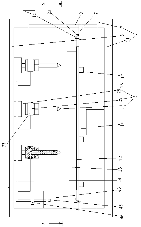
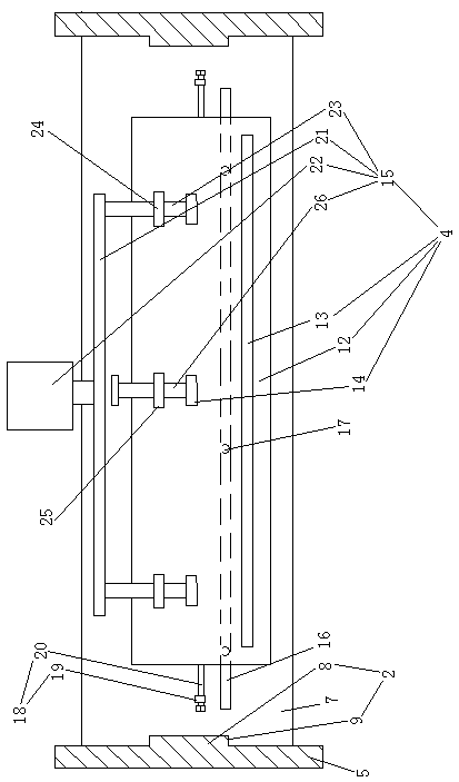
[0029] Embodiment one, see figure 1 , figure 2 and image 3 , a line rail drilling machine, including a frame 1, a drilling mechanism 2, a number of drill assemblies 3 distributed along the lateral direction and a line rail fixing mechanism 4 located below the drill assembly.
[0030] The frame 1 includes two uprights 5 , a beam 6 connected to the upper end of the uprights, a supporting plate 7 and a ground beam 11 connected to the lower end of the uprights.
[0031] The drilling mechanism includes two horizontally distributed vertical slide rails 8, two chutes 9 and a pallet lifting mechanism 10. The two vertical slide rails are arranged on the two columns correspondingly. The two slide grooves are correspondingly arranged at both ends of the supporting plate in the transverse direction. The two vertical slide rails are correspondingly arranged in the two slide grooves one by one. The supporting plate lifting mechanism can be manually driven by a jack at this time, or i...
Embodiment 2
[0036] Embodiment two, point out as the difference with embodiment one:
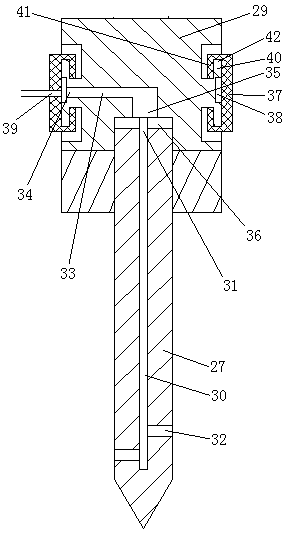
[0037] see Figure 5 , The coolant storage tank 43 is a sealed structure. A pressure relief valve 49 is provided on the top wall of the coolant storage tank. The coolant storage tank is provided with a liquid outlet start-up structure. The liquid outlet start-up structure includes a slide tube 50 connected to the coolant storage tank and a slide block 51 slidably and sealingly connected in the slide tube. The slide pipe is provided on the top wall of the coolant storage tank. The slider is connected with a slider part driving rod 52 . One end of the slide tube raw material slide block connecting rod is closed by the end wall 52 . The sliding block cooperates with the end wall to isolate the pressurization chamber 53 in the sliding tube. The pressurized chamber is provided with an air outlet 54 communicating with the interior of the coolant storage tank. The opening direction of the air outlet is h...
PUM
 Abstract
Description
Claims
Application Information