Trajectory tracking control methods and trajectory tracking systems

A control method and trajectory tracking technology, which is applied in the direction of program control manipulators, manufacturing tools, manipulators, etc., can solve the problems of large trajectory tracking error, unrealizable, cumbersome tracking system, etc.

Active Publication Date: 2019-11-15
SUZHOU RUINIU ROBOT TECH CO LTD
View PDF6 Cites 8 Cited by
  • Summary
  • Abstract
  • Description
  • Claims
  • Application Information

AI Technical Summary

Problems solved by technology

This method is based on the track deviation information detected by the sensor. If it is unbiased and not corrected, then even if there is no deviation in the current position of the tool, after advancing according to the predetermined task track, the tool position will also deviate at the next moment, so the whole process cannot be realized theoretically. Unbiased tracking can only reduce the deviation to no more than the new deviation caused by each step forward, so the purpose of trajectory tracking can be better achieved only when the radius of curvature o...

Method used


Image

  • Trajectory tracking control methods and trajectory tracking systems
  • Trajectory tracking control methods and trajectory tracking systems
  • Trajectory tracking control methods and trajectory tracking systems

Examples


Embodiment 1

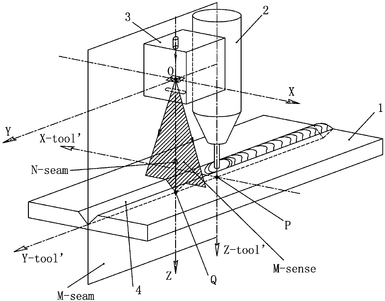
[0135] In the trajectory tracking control method described in this embodiment, the tool 2 is attached to the actuator, the sensor 3 is attached to the joint of the actuator or the sensor 3 is directly attached to the tool 2, and the relative position between the sensor 3 and the tool 2 has The determined geometric relationship specifically includes the following steps:

[0136] The first step: detection trajectory: the original trajectory information of the detection point on the trajectory on the workpiece 1 is collected by the sensor 3. The sensor 3 involved here can convert the detected visual information into the original trajectory information. At present, this type of sensor is generally a visual sensor , the present invention is described by taking a typical structured light vision sensor as an example.

[0137] The second step: Extract trajectory information: extract the position information of the detection point from the original trajectory information, and express t...

Embodiment 2

[0179] The difference between this embodiment and Embodiment 1 is that this embodiment is based on the reference point Ref-A, and instead of using the above-mentioned current control reference point Ref-A as the tracking target, it uses the control interval time t The subsequent control reference point Ref-A-next is the tracking target. In this embodiment, according to the trajectory position information set {Q}, the specific determination method for determining the target position of tool 2 at the next moment is as follows: take the reference point Ref-A as the center of the sphere, and use △=V*t as the radius to make a spherical surface, the There are two intersection points between the spherical surface and the characteristic line of the trajectory. Take the intersection of the spherical surface and the characteristic line of the trajectory in the forward direction of the tool as the control reference point Ref-A-next, and take the control reference point Ref-A-next as the t...

Embodiment 3

[0184] The difference between this embodiment and the first embodiment is that in the fourth step of determining the target, this embodiment determines the target position and attitude of the tool 2 at the next moment based on the track position information set {Q}, and also Further obtain the position and attitude deviation information between the target position of the tool 2 at the current moment and the target position of the tool at the next moment. The specific development of other steps of the trajectory tracking control method is the same as that of the first embodiment, and will not be repeated here. The specific trajectory tracking control method includes the following steps:

[0185] The first step: detecting the trajectory: the original trajectory information of the trajectory detection point on the workpiece is collected by the sensor 3 .

[0186] The second step: Extract trajectory information: extract the position information of the detection point from the orig...


PUM


Abstract

The invention discloses four trajectory tracking control methods and trajectory tracking systems corresponding to the trajectory tracking control methods. The basic ideas of the four trajectory tracking control methods are consistent, trajectory information which is obtained through a sensor and described through a variable sensor coordinate system is fixed firstly, that is, after detection, the information is converted to be suitable for being marked in a form of being described by the coordinate system for overall recording the trajectory information, a real trajectory is shown step by step,a basis is provided for the subsequent solution target, finally, according to the target, the ideal state which should be shown by a tool at the current moment is found, or the state about to be achieved when the correction moment of next time arrives after correction of the this time is completed is found, and then an executer is driven according to the above information to correct the trajectory of the tool. According to the four trajectory tracking control methods and the trajectory tracking systems corresponding to the trajectory tracking control methods, errors brought by detecting pointadvancing are overcome, the methods can be separated from teaching information to independently run, position deviation of the tool can be corrected, posture deviation of the tool can also be corrected, and the trajectory tracking effect is good.

Description

technical field [0001] The invention relates to the technical field of automatic trajectory tracking, in particular to a trajectory tracking control method and a trajectory tracking system for realizing the trajectory tracking control method. Background technique [0002] Welding, gluing, cutting and other operations are similar routine operations, and their common feature is to operate along a specific trajectory. If the specific trajectory position can be detected by sensors, the trajectory can be adjusted by robots and other actuators. Tracking to automate jobs. [0003] Advanced ones in existing trajectory tracking systems use sensors to track trajectories, for example, arc welding robot systems use structured light vision sensors to track trajectories. The actuator in the trajectory tracking system itself has a predetermined task trajectory through teaching information or planning, and the actuator with the tool can generate driving information according to the predete...

Claims


Application Information

Patent Timeline
IPC IPC(8): B25J9/16B25J13/08
CPCB25J9/1605B25J9/1664B25J9/1694B25J13/08B25J13/088
Inventor 吕伟新熊斌朱杰郭振杰王磊
Owner SUZHOU RUINIU ROBOT TECH CO LTD
Why Eureka
Try Eureka