Hot gas distributor for active control over turbine gap, platform and method

An active control, distributor technology, applied in the direction of engine components, machines/engines, leakage prevention, etc.

Inactive Publication Date: 2019-11-15
AECC SHENYANG ENGINE RES INST
View PDF5 Cites 0 Cited by
  • Summary
  • Abstract
  • Description
  • Claims
  • Application Information

AI Technical Summary

Problems solved by technology

[0006] The purpose of this application is to provide a hot gas distributor, platform and control method for act

Method used


Image

  • Hot gas distributor for active control over turbine gap, platform and method
  • Hot gas distributor for active control over turbine gap, platform and method
  • Hot gas distributor for active control over turbine gap, platform and method

Examples


Embodiment Construction

[0033] In order to make the purpose, technical solution and advantages of the application more clear, the technical solution in the embodiment of the application will be described in more detail below in conjunction with the drawings in the embodiment of the application.

[0034] In order to solve the existing variable gap test scheme, the turbine test piece needs to go up and down repeatedly, repeated disassembly and assembly reduces the test work efficiency, increases the test cost, and repeated assembly leads to multiple assemblies that provide assembly errors, while the test results To solve the problem of impact, the present application provides a hot gas distributor, platform and method for active control of turbine clearance.

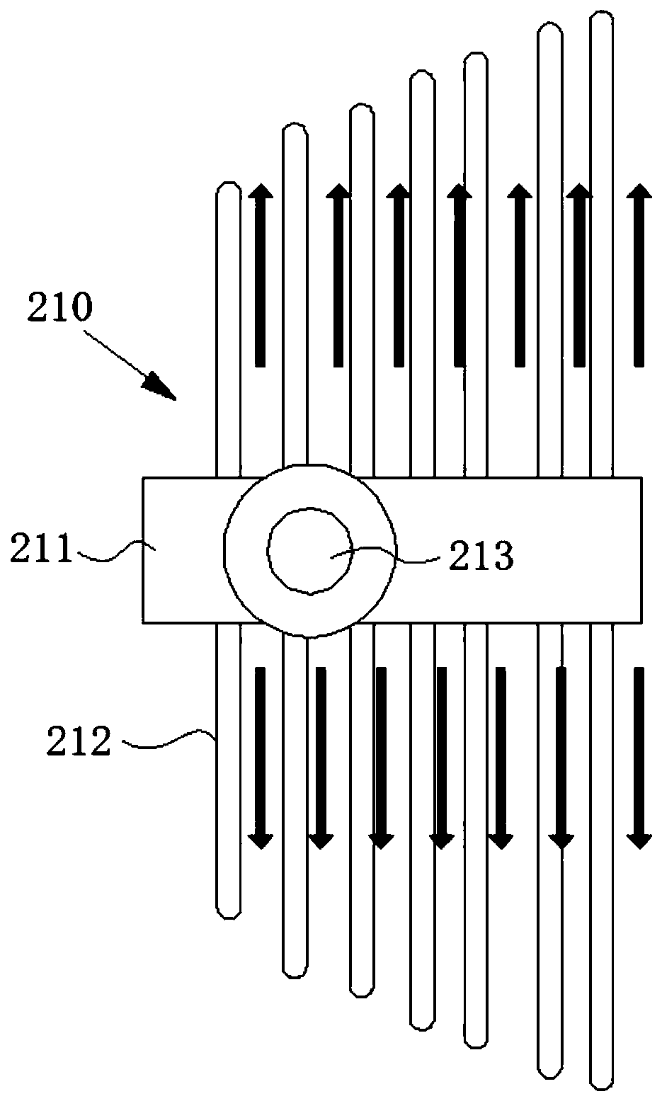
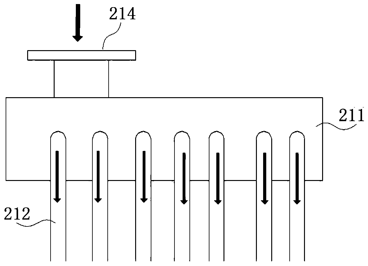
[0035] like figure 2 and image 3 As shown, the hot gas distributor 210 for the active control of the turbine gap provided by the present application includes a plurality of jet tubes 212 and at least one gas collection chamber 211 extending su...


PUM


Abstract

The invention relates to a hot gas distributor for active control over a turbine gap. The hot gas distributor comprises a plurality of jet tubes surrounding an outer casing and at least one gas collecting cavity extending in the axial direction of the outer casing; the jet tubes are provided with a plurality of vent holes at least partially facing the outer casing, each gas collecting cavity is provided with an inlet and an outlet, the gas collecting cavities are in communication with the jet tubes, and when hot gas flows in from the inlets of the gas collecting cavities and flows out from thevent holes of the jet tubes, the outer casing can swell in the axial direction of the outer casing to change the blade tip gap between a movable blade in the outer casing and the outer casing. According to the hot gas distributor, the hot gas is introduced into the gas collecting cavities and is then distributed to the jet tubes at all positions, the hot gas is discharged out through air holes inthe jet tubes, the outer casing of a turbine test piece is impacted, the outer casing is heated to expand, the purpose of changing the blade tip gap is achieved, and the significant advantage of being controllable in gap change is achieved.

Description

technical field [0001] The application belongs to the technical field of turbine testing, and in particular relates to a hot gas distributor, platform and method for active control of turbine clearance. Background technique [0002] Aeroengine turbine tip clearance usually refers to the radial gap between the engine turbine rotor blades and the casing, and the flow in the tip clearance is driven by the pressure difference between the pressure surface and the suction surface of the blade, and flows from the pressure surface to the suction surface. The blade tip leakage vortex is generated in the flow process of mainstream mixing, which in turn produces a large flow loss, which eventually leads to a decrease in turbine efficiency. Studies have shown that every 1% increase in the ratio of the tip clearance to blade height of a high-pressure turbine will cause a decrease in turbine efficiency by about 1.5%. And every 0.254mm reduction in tip clearance can reduce specific fuel c...

Claims


Application Information

Patent Timeline
IPC IPC(8): F01D11/24F01D21/00F01D25/00
CPCF01D11/24F01D21/00F01D21/003F01D25/00
Inventor 崔丕龙杨建伟马永峰郝晟淳陈强才彦双张爱武林田琦张东海赵展
Owner AECC SHENYANG ENGINE RES INST
Why Eureka
Try Eureka