
Vertical specially-shaped magnetic shielding cylinder

A magnetic shielding cylinder and magnetic shielding technology, applied in the field of magnetic shielding, can solve the problems of reduced shielding performance of the shielding room, large size of the magnetic shielding room, loss of magnetic permeability, etc., so as to improve the flexibility of use, reduce the magnetic flux leakage between the door gap, Effect of Improving Shielding Performance

Pending Publication Date: 2021-12-14
北京零磁科技有限公司
View PDF0 Cites 0 Cited by
  • Summary
  • Abstract
  • Description
  • Claims
  • Application Information

AI Technical Summary

Problems solved by technology

[0008] For this reason, the present invention provides a vertical special-shaped magnetic shielding cylinder to solve the problem that the magnetic shielding chambers in the prior art are relatively large in size and heavy in mass, and require on-site construction and construction. After construction, the use position cannot be changed, and the cost is also relatively high. High, and, the existing magnetic shielding room using high magnetic permeability permalloy is to stick the heat-treated permalloy plate on the non-magnetic skeleton, because the magnetic permeability of permalloy after heat treatment will be affected by external stress , mechanical deformation and welding and other factors, so each piece of permalloy cannot be welded on site after heat treatment. Each piece of permalloy is pasted on the skeleton with adhesive, and there will be large or Small gaps, resulting in magnetic flux leakage at the gaps
At the same time, during the construction and assembly process, the magnetic permeability will also be lost due to external force and deformation. These factors will lead to the decline of the shielding performance of the entire shielding room.

Method used


Image

  • Vertical specially-shaped magnetic shielding cylinder
  • Vertical specially-shaped magnetic shielding cylinder
  • Vertical specially-shaped magnetic shielding cylinder

Examples


Embodiment 1

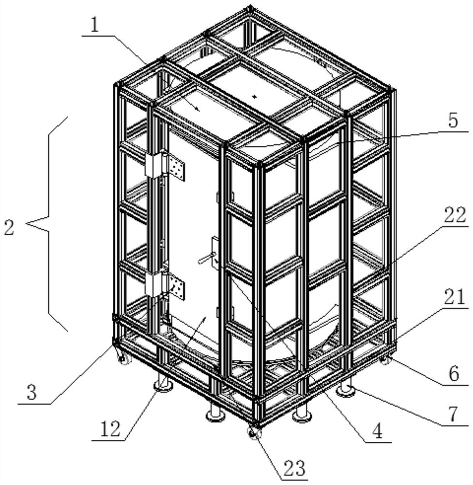
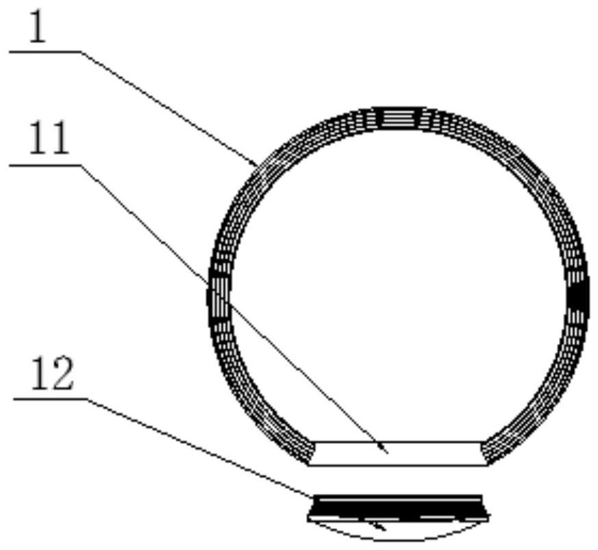
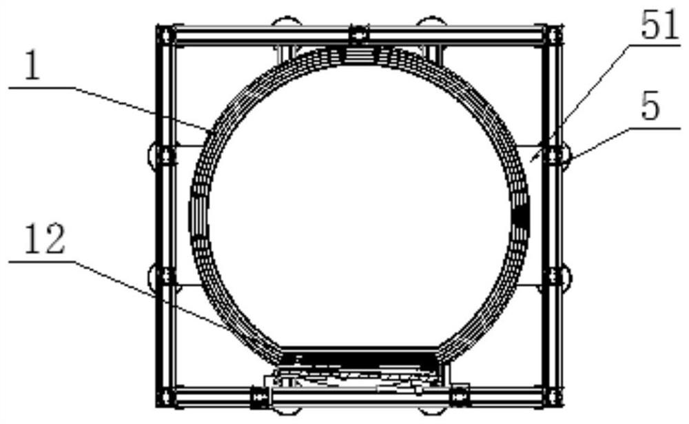
[0035] For a vertical special-shaped magnetic shielding cylinder provided in Embodiment 1 of the present invention, please refer to figure 1 and figure 2 As shown, it includes: a magnetic shielding tube 1 , a magnetic shielding door 12 and a mobile support frame 2 .

[0036] Specifically, there is a door opening 11 on the side wall of the magnetic shielding tube 1, the cross section of the magnetic shielding tube 1 is an arc structure larger than half a circle, and the cross section of the door opening 11 is a straight line structure; the magnetic shielding door 12 matches the door opening 11; The magnetic shielding cylinder 1 is vertically installed on the mobile support frame 2 .

[0037] Wherein, the mobile support frame 2 includes a base 21, the top of the base 21 is connected with a frame 22, the magnetic shielding cylinder 1 is installed on the top of the base 21, the magnetic shielding cylinder 1 is fixedly connected with the frame 22, and one side of the frame 22 is ...

Embodiment 2

[0046] For a vertical special-shaped magnetic shielding cylinder provided in Embodiment 2 of the present invention, please refer to figure 1 and figure 2 As shown, it includes: a magnetic shielding tube 1 , a magnetic shielding door 12 and a mobile support frame 2 .

[0047] Specifically, there is a door opening 11 on the side wall of the magnetic shielding tube 1, the cross section of the magnetic shielding tube 1 is an arc structure larger than half a circle, and the cross section of the door opening 11 is a straight line structure; the magnetic shielding door 12 matches the door opening 11; The magnetic shielding cylinder 1 is vertically installed on the mobile support frame 2 .

[0048] Wherein, the mobile support frame 2 includes a base 21, the top of the base 21 is connected with a frame 22, the magnetic shielding cylinder 1 is installed on the top of the base 21, the magnetic shielding cylinder 1 is fixedly connected with the frame 22, and one side of the frame 22 is ...

Embodiment 3

[0057] For a vertical special-shaped magnetic shielding cylinder provided in Embodiment 3 of the present invention, please refer to figure 1 and figure 2 As shown, it includes: a magnetic shielding tube 1 , a magnetic shielding door 12 and a mobile support frame 2 .

[0058] Specifically, there is a door opening 11 on the side wall of the magnetic shielding cylinder 1, which can accommodate at least one adult to enter and exit normally; the magnetic shielding door 12 matches the door opening 11;

[0059] Wherein, the mobile support frame 2 includes a base 21, the top of the base 21 is connected with a frame 22, the magnetic shielding cylinder 1 is installed on the top of the base 21, the magnetic shielding cylinder 1 is fixedly connected with the frame 22, and one side of the frame 22 is provided with a magnetic shielding door 12 for opening. The opening 23 . At least one caster 6 is provided at the four corners of the bottom of the base 21 respectively. An anchor 7 is pro...


PUM


Abstract

The invention discloses a vertical specially-shaped magnetic shielding cylinder comprising a magnetic shielding cylinder body, a magnetic shielding door and a movable supporting frame, a door opening is formed in the side wall of the magnetic shielding cylinder body, and the magnetic shielding door is matched with the door opening; the magnetic shielding cylinder is vertically installed on the movable supporting frame. A finished product is manufactured in advance and moved to the site to be directly used without being installed on the site, efficiency is improved, the position can be moved at any time in the using process, and using flexibility is improved. The vertical specially-shaped magnetic shielding cylinder is arranged to be of an integral structure, on-site splicing and welding are not needed, the magnetic conductivity of permalloy is prevented from being lost due to external force and deformation, so that the purpose of improving the shielding performance of the whole shielding cylinder is achieved. The magnetic shielding cylinder is seamless under the condition of the integral structure, so that the purpose of no magnetic leakage is achieved.

Description

technical field [0001] The invention belongs to the technical field of magnetic shielding, and in particular relates to a vertical special-shaped magnetic shielding cylinder. Background technique [0002] With the rapid development of modern industrial technology, all kinds of electronic products have emerged as the times require. Digital and high-low frequency electronic equipment will also radiate a large number of electromagnetic waves of different wavelengths into the space when they are working. Electromagnetic radiation pollution has become the main obstacle for high-precision weak magnetic field measurement. . Magnetic shielding is mainly used in atomic time-frequency systems, magnetic sensor calibration, inertial gyroscopes, fiber optic gyroscopes, laser gyroscopes, and precision instruments. The function of the magnetic shielding device is to shield the earth's magnetic field and the stray magnetic field of the environment outside the magnetic shielding device, and...

Claims


Application Information

Patent Timeline
Patent Type & Authority Applications(China)
IPC IPC(8): H05K9/00
CPCH05K9/0001
Inventor 崔利亚孙永红潘可
Owner 北京零磁科技有限公司
Learn More