
Inlet distortion constraint device and centrifugal compressor provided with same

A technology of centrifugal compressors and restraint devices, which is applied to the parts of pumping devices for elastic fluids, mechanical equipment, non-variable pumps, etc., and can solve the problems of compressor efficiency attenuation, aggravated shaft system fluctuations, complex construction, etc. problem, to achieve the effect of improving reliability, reducing impact impact, and simple device structure

Inactive Publication Date: 2019-11-15
康跃科技(山东)有限公司
View PDF0 Cites 4 Cited by
  • Summary
  • Abstract
  • Description
  • Claims
  • Application Information

AI Technical Summary

Problems solved by technology

[0012] Aiming at the deficiencies in the prior art, the present invention provides an intake distortion restriction device and a centrifugal compressor with the device, which are used to solve the problems caused by the intake air flow introduced into the centrifugal compressor in the compact system in the traditional technology, resulting in compressed air The efficiency attenuation of the compressor and the aggravation of shafting fluctuations; and the installation of complex components will result in complex construction, high cost, and even increase the failure rate of compressor operation

Method used


Image

  • Inlet distortion constraint device and centrifugal compressor provided with same
  • Inlet distortion constraint device and centrifugal compressor provided with same
  • Inlet distortion constraint device and centrifugal compressor provided with same

Examples


Embodiment 1

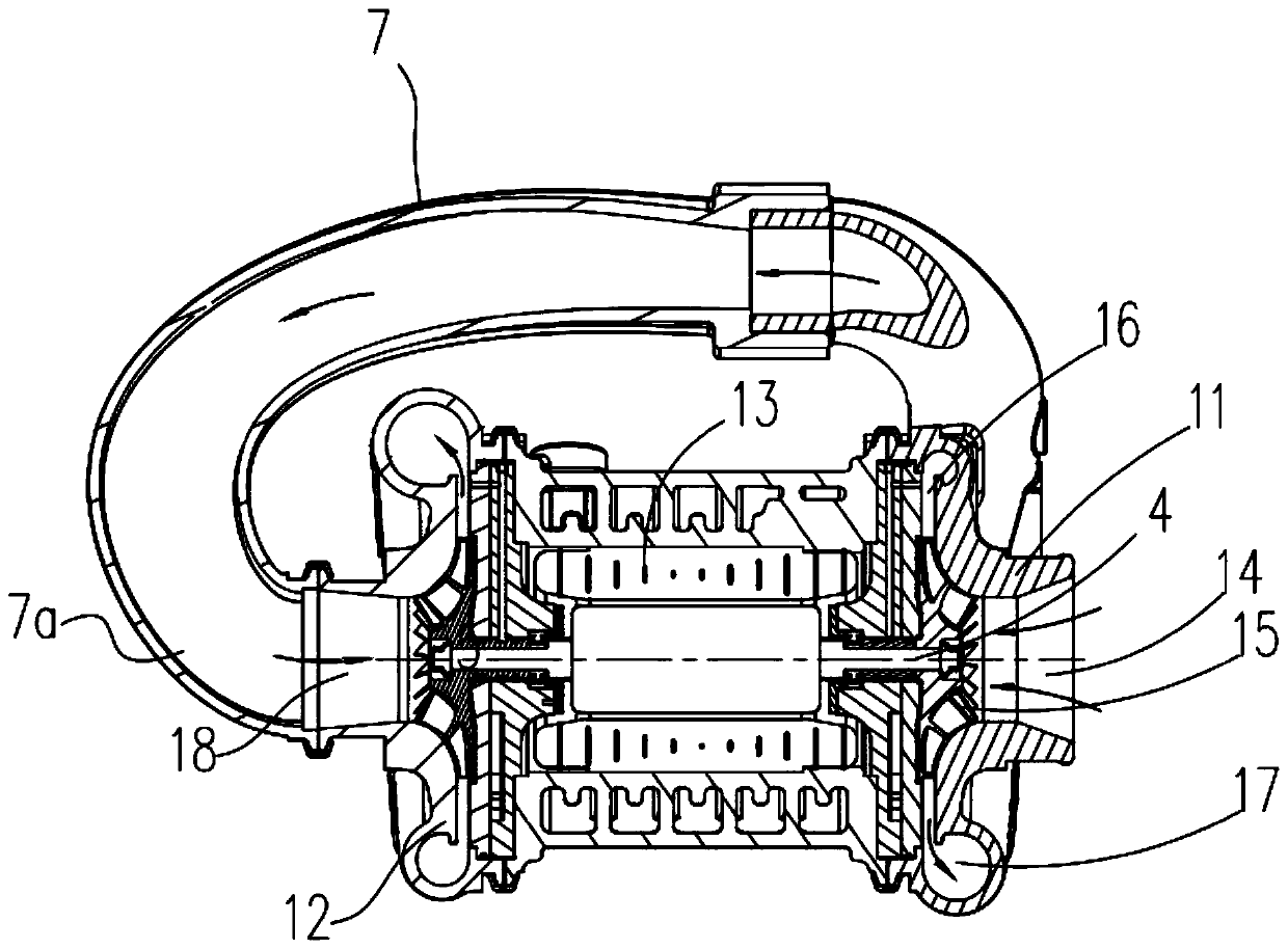
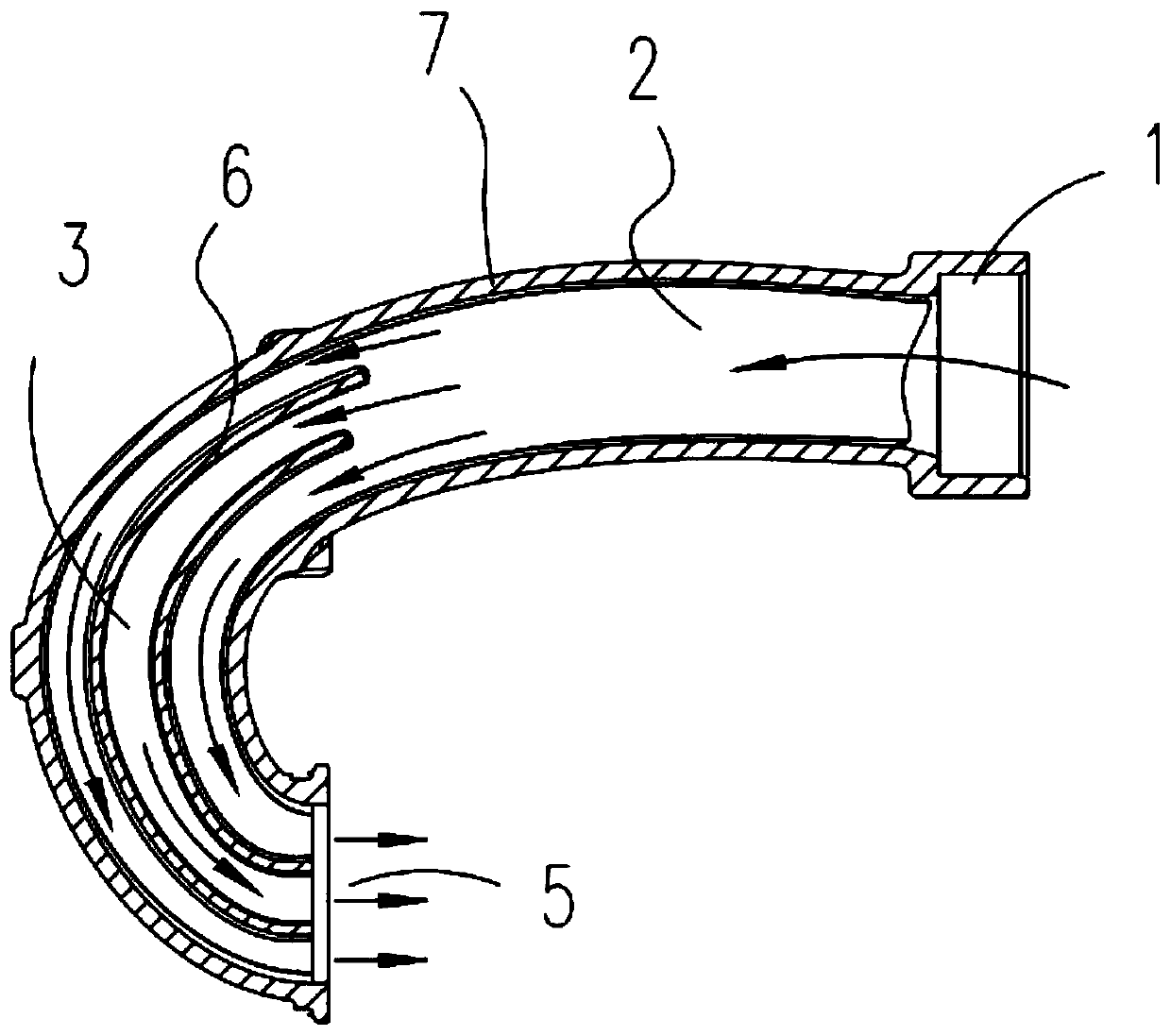
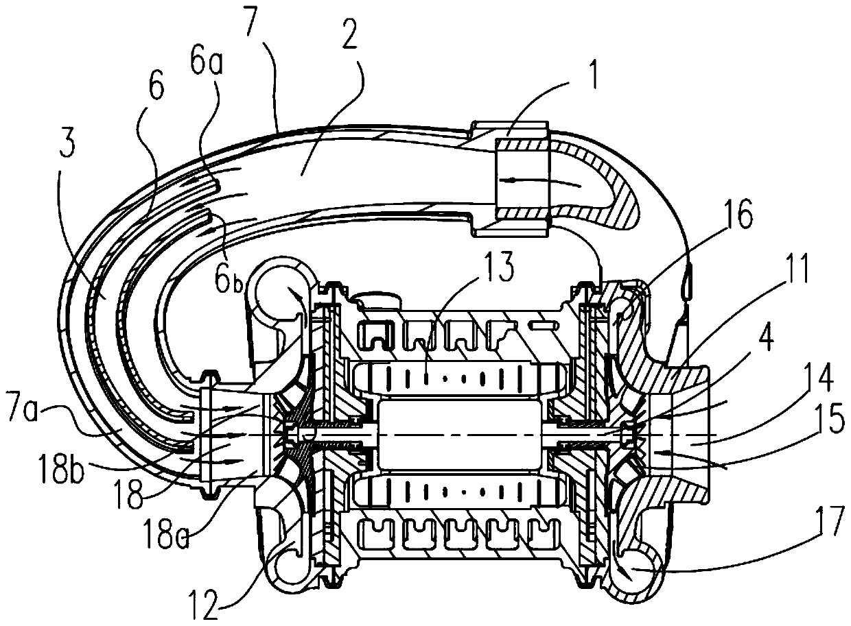
[0040] Such as Figure 1 to Figure 4 as well as Figure 10 As shown, the intake distortion restriction device and the centrifugal compressor with the device include a guide tube, and the inner cavity of the guide tube 7 is provided with a stabilizing plate 6 for rectifying the turbulent air flow along its guide direction, and the centrifugal compressor The low-pressure stage compressor casing flow channel 17 of the low-pressure stage air outlet is connected to the intake end of the guide pipe 7, and the air outlet end of the guide pipe 7 is connected to the high-pressure stage air inlet of the centrifugal compressor.

[0041] The inner cavity of the guide tube 7 is divided into a drainage channel 2 and a diversion channel 3 in sequence along the air intake direction, and the stabilizing plate 6 is located in the diversion channel 3 .

[0042] Drainage channel 2, the function of the drainage channel 2 is to evenly distribute the pressurized gas passing through the gas inlet part...

Embodiment 2

[0064] Such as Figure 5 As shown, the difference between this embodiment and the first embodiment lies in the shape of the flow stabilizing plate, which includes two juxtaposed plate bodies that gradually change with the shape of the draft tube.

Embodiment 3

[0066] Such as Figure 6 As shown, the difference between this embodiment and Embodiments 1 and 2 lies in the shape of the stabilizing plate. The stabilizing plate includes two plates that gradually change with the shape of the draft tube, and the two plates along the longitudinal section of the air inlet The direction is set in a criss-cross pattern.


PUM


Abstract

The invention provides an inlet distortion constraint device and a centrifugal compressor provided with the same, and relates to the technical field of an inlet airflow rectifying device of the centrifugal compressor. The inlet distortion constraint device comprises a flow guide pipe, wherein flow stabilizing plates used for rectifying turbulent airflow are arranged in an inner cavity of the flowguide pipe in the flow guiding direction. According to the inlet distortion constraint device and the centrifugal compressor provided with the same, the problems of efficiency attenuation of a gas compressor and increase of shafting fluctuation due to introduction of inlet airflow into the centrifugal compressor in a compact system in a traditional technology are solved; and the problems of complicated construction, high cost and even increase of operating failure rate of the compressor due to arrangement of complex parts are solved.

Description

technical field [0001] The invention relates to the technical field of rectification devices for intake air flow of centrifugal compressors, in particular to an intake distortion restriction device and a centrifugal compressor with the device. Background technique [0002] With the development of industrial technology, there is more and more demand for high-pressure gas in specific occasions, and centrifugal compressors are more popular than screw and scroll compressors because of their superior performance and environmental protection characteristics. . In order to obtain a higher degree of gas pressurization, many occasions have adopted a sequential series of two-stage pressurization or even a multi-stage pressurization structure. Most of the supercharged structures adopt the form of centrifugal compressors; the most basic condition that a qualified centrifugal compressor should meet is that a steady-state airflow is formed between the two-stage compressors. , to ensure ...

Claims


Application Information

Patent Timeline
IPC IPC(8): F04D29/44F04D29/66
CPCF04D29/441F04D29/667
Inventor 李延昭张林营孙金辉苏益龙司英杰信效芬
Owner 康跃科技(山东)有限公司
Learn More