Multi-flow spiral winding pipe type efficient heat exchanger
A tubular heat exchanger, spiral winding technology, applied in the direction of heat exchanger type, heat exchanger shell, indirect heat exchanger, etc., can solve the problem of damage to heat exchange tubes, low utilization of tube sheets, and easy vibration in the transition section and other problems, to achieve the effect of improving service life, reducing unsupported span, and simple structure
- Summary
- Abstract
- Description
- Claims
- Application Information
AI Technical Summary
Problems solved by technology
Method used
Image
Examples
Embodiment 1
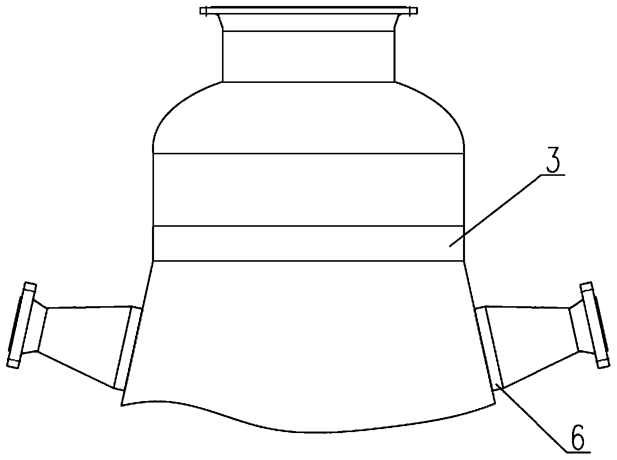
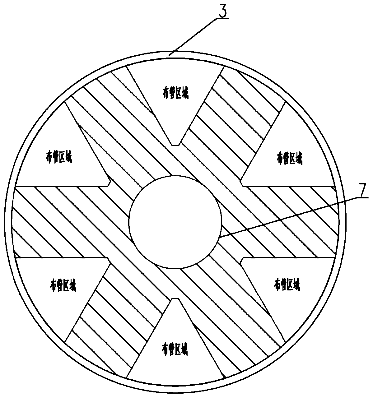
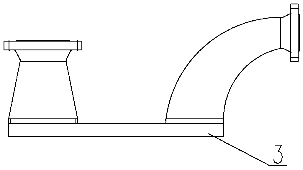
[0043] Such as Figure 5-Figure 8 As shown, a multi-stream spiral wound tube heat exchanger includes a shell 8, and the two ends of the shell 8 are respectively provided with axial tube sheets 3, and are installed between the two axial tube sheets 3 There is a central cylinder 7 on which multilayer heat exchange tubes 4 are wound in a helical shape to form a winding section, and the helical directions of two adjacent layers of heat exchange tubes 4 are opposite; the two ends of each heat exchange tube 4 are respectively connected to the corresponding The tube holes on the axial tube sheet 3 are connected, and the heat exchange tube is a transition section from the winding section to the axial tube sheet; the upper and lower parts of the shell 8 are respectively provided with a shell-side nozzle corresponding to the transition section. 11. Outer tube boxes 2 are respectively provided at both ends of the shell 8. The outer tube box 2 is composed of a cylinder and an oval head. T...
Embodiment 2
[0050] On the basis of the multi-stream spirally wound tube heat exchanger in Embodiment 1, the shapes of the inner tube box 1 and the outer tube box 2 are adjusted. Such as Figure 9 As shown, the outer tube box 2 is composed of a cylinder and a conical head, and the top of the outer tube box 2 is provided with an axial outer tube pass nozzle 13; the inner tube box 1 is composed of a cylinder and an elliptical head, and the inner tube The box 1 is placed in the outer tube box 2, and the inner tube box 1 is provided with a radial inner tube pass nozzle 12, and the radial tube pass nozzle passes through the side wall of the outer tube box 2. The outer tube box 2 is coaxial with the inner tube box 1 so as to form two independent space pipe layout areas on the axial tube plate 3, to the tube layout area inside the outer tube box 2 and the tube layout area formed by the inner and outer tube boxes Different process fluids are fed into the tubes, and the process fluids enter the he...
PUM
 Abstract
Description
Claims
Application Information
 - R&D
- Intellectual Property
- Life Sciences
- Materials
- Tech Scout
- Unparalleled Data Quality
- Higher Quality Content
- 60% Fewer Hallucinations
Browse by: Latest US Patents, China's latest patents, Technical Efficacy Thesaurus, Application Domain, Technology Topic, Popular Technical Reports.
© 2025 PatSnap. All rights reserved.Legal|Privacy policy|Modern Slavery Act Transparency Statement|Sitemap|About US| Contact US: help@patsnap.com


