Eureka AIR delivers breakthrough ideas for toughest innovation challenges, trusted by R&D personnel around the world.

Micro-structural damping cylinder vortex-induced vibration experimental device and simulation method

A vortex-induced vibration and microstructure technology, which is used in submarine pipeline engineering and offshore engineering, and can solve problems such as large uncertainty in system damping

Active Publication Date: 2019-11-15
INST OF MECHANICS - CHINESE ACAD OF SCI
View PDF7 Cites 8 Cited by
  • Summary
  • Abstract
  • Description
  • Claims
  • Application Information

AI Technical Summary

Problems solved by technology

Most of the existing experimental devices use multiple sets of fixed pulleys and guide rails for guidance. Due to friction, collision and jamming between the guide rails and pulleys, the system has large damping and uncertainty.

Method used

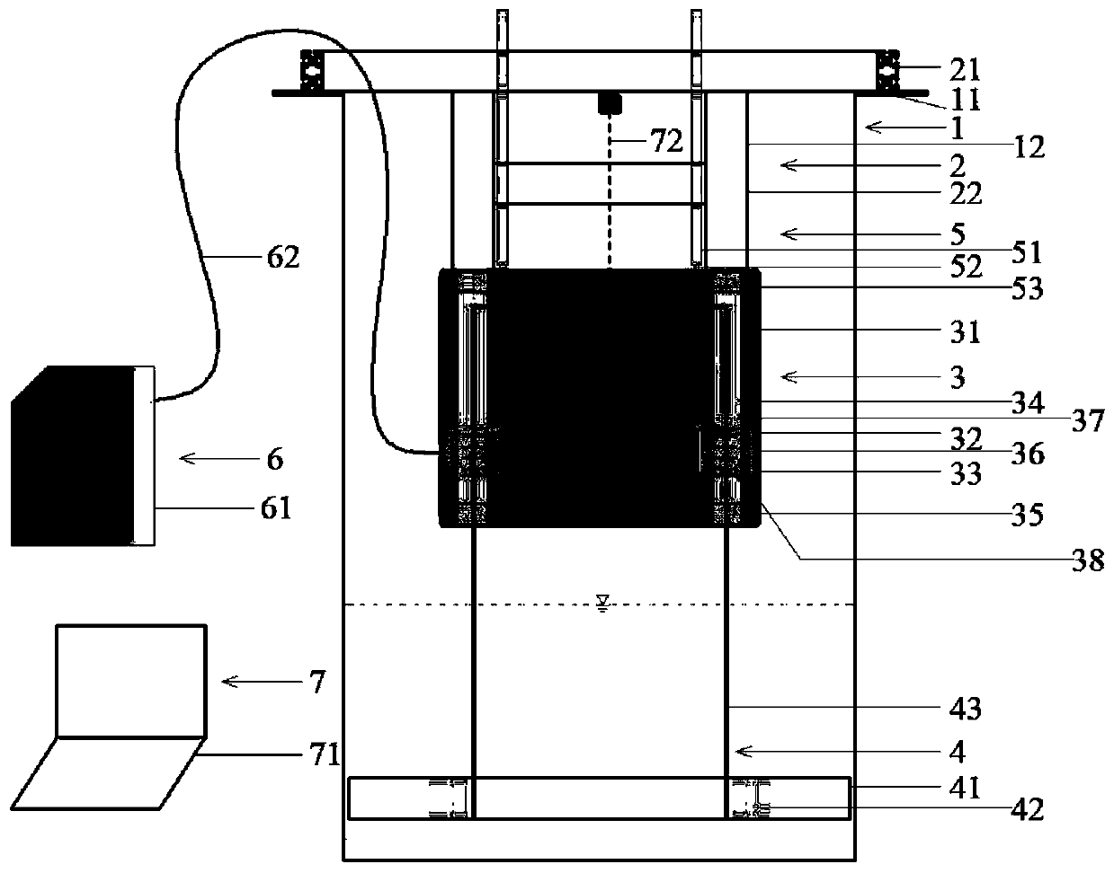

Image

  • Micro-structural damping cylinder vortex-induced vibration experimental device and simulation method
  • Micro-structural damping cylinder vortex-induced vibration experimental device and simulation method
  • Micro-structural damping cylinder vortex-induced vibration experimental device and simulation method

Examples


Embodiment 1

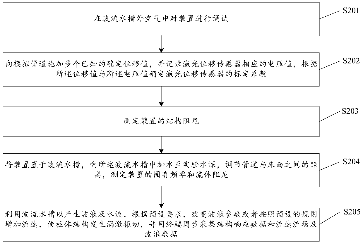
[0067] 1. Debug the device in the air outside the wave flow tank;

[0068] 2. Apply multiple known definite displacement values ​​to the simulated pipeline, and record the corresponding voltage value of the laser displacement sensor, and obtain the calibration coefficient of the laser displacement sensor by fitting the displacement and the corresponding voltage value;

[0069] 3. To measure the structural damping of the device, the basic operation is as follows: a. Apply a known displacement excitation to the cylinder and release it, allowing it to freely attenuate the vibration; b. Record the change of the vibration displacement of the cylinder with time; c. Matching theoretically predicted responses with experimental records to find unknown damping;

[0070] 4. Hoist the device into the experimental section of the wave flow tank, add water to the water tank to the test water depth, and adjust the distance between the pipeline and the bed surface. Measuring the natural frequ...

Embodiment 2

[0073] 1. Debug the device in the air outside the wave flow tank;

[0074] 2. Apply multiple known definite displacement values ​​to the simulated pipeline, and record the corresponding voltage value of the laser displacement sensor, and obtain the calibration coefficient of the laser displacement sensor by fitting the displacement and the corresponding voltage value;

[0075] 3. To measure the structural damping of the device, the basic operation is as follows: a. Apply a known displacement excitation to the cylinder and release it, allowing it to freely attenuate the vibration; b. Record the change of the vibration displacement of the cylinder with time; c. Matching theoretically predicted responses with experimental records to find unknown damping;

[0076] 4. Hoist the device into the experimental section of the wave flow tank, add water to the water tank to the test water depth, and adjust the distance between the pipeline and the bed surface. Measuring the natural frequ...


PUM


Abstract

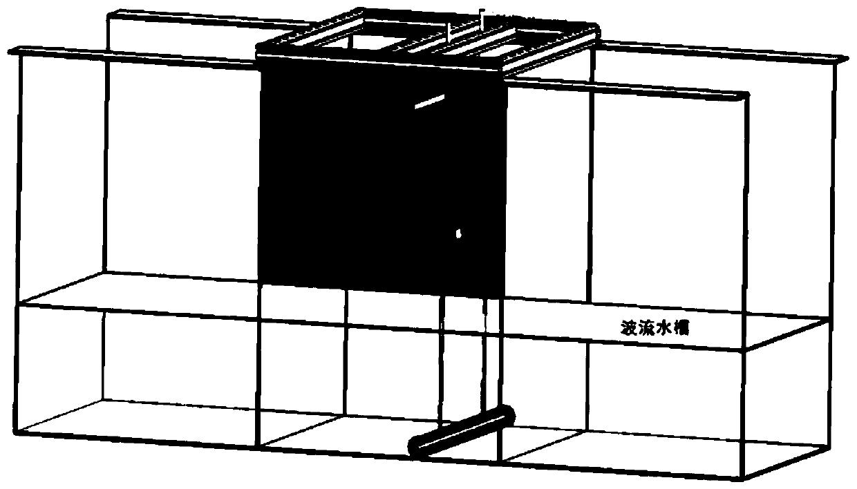
The embodiment of the invention relates to a micro-structural damping cylinder vortex-induced vibration experimental device and a simulation method. The device comprises a large wave current water tank module, a liftable support module, a gas floating platform module, a cylinder structure module, a spring module, a gas path module and a measurement module. The device can research cylinder structural vortex-induced vibration triggering and amplitude-frequency response characteristics, in particular nearly bed surface cylinder vortex-induced vibration, submarine pipeline vortex-induced vibration, the seabed scouring coupling effect and the like; and the result can provide scientific basis for an engineer to design and lay a submarine pipeline.

Description

technical field [0001] The embodiments of the present invention relate to the technical fields of offshore engineering and submarine pipeline engineering, and in particular to an experimental device and simulation method for vortex-induced vibration of a cylinder with microstructure damping. Background technique [0002] Submarine pipeline is an important part of the offshore oil and gas field exploitation system. It has been widely used due to its high production efficiency and is known as the lifeline of the offshore oil and gas field. Different from onshore oil and gas transportation, submarine pipelines are affected by many factors such as harsh marine environmental loads and complex submarine topography, and their safety has always been the focus of attention. The causes of damage to submarine pipelines usually include third-party damage, scouring suspension, corrosion, etc. Submarine pipelines laid on the seabed often have suspended sections under the pipeline due to ...

Claims


Application Information

Patent Timeline
IPC IPC(8): G01M7/02G01M10/00
CPCG01M7/02G01M10/00
Inventor 刘俊高福平
Owner INST OF MECHANICS - CHINESE ACAD OF SCI
Why Eureka
Eureka Blog
Learn More