Intelligent direct current monitoring system and method
An intelligent monitoring and direct current technology, applied in the direction of measuring current/voltage, measuring devices, and measuring electrical variables, etc., can solve the problems affecting the optimization of cabinet resource layout, the improvement of test scheduling area balance business, and the impact of assembly DC utilization and exhaustion. Process efficiency, affecting test results and test efficiency, etc., to achieve the effect of improving the DC power utilization rate of the assembly, improving the DC power utilization rate of the assembly and scheduling efficiency, and improving the balance of the test scheduling area
- Summary
- Abstract
- Description
- Claims
- Application Information
AI Technical Summary
Problems solved by technology
Method used
Image
Examples
Embodiment 1
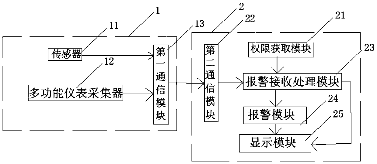
[0042] Please refer to figure 1 , the direct current intelligent monitoring system of the present invention includes: a monitoring device 1 for collecting current signals / voltage signals for monitoring, and a communication connection with the monitoring device 1 for graphically displaying information transmitted by the monitoring device 1 Data, monitoring equipment 2 that sends out alarm information according to the processing results, reproduces faults, and statistically analyzes historical data.
[0043] Specifically, the monitoring device 1 includes: a sensor 11 installed on the power supply copper bar for collecting the current signal of the copper bar, and a multifunctional instrument collector 12 connected to the copper bar for collecting voltage signals And the first communication module 13 for transmitting the data information collected by the sensor 11 and the multi-function meter collector 12 to the monitoring device 2 . The sensor 11 is a Hall sensor.
[0044] The...
Embodiment 2
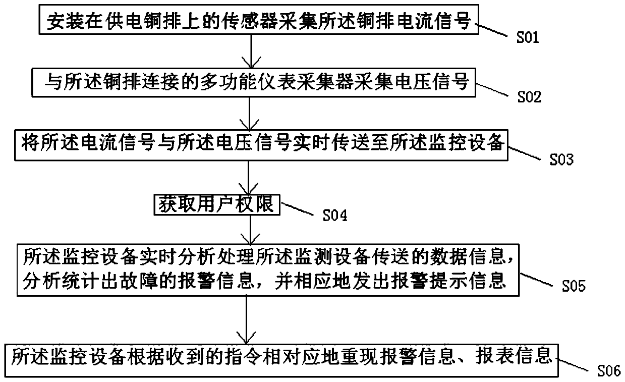
[0047] Please refer to figure 2 , the direct current intelligent monitoring method of the present invention, comprises the steps:
[0048] S01. The sensor installed on the power supply copper bar collects the current signal of the copper bar. Specifically, the Hall sensor is installed on the power supply copper bar of the device to be tested, and the current signal on the copper bar is collected in real time.
[0049] S02. A multi-function instrument collector connected to the copper bar collects voltage signals. Specifically, the multi-function instrument collector is directly connected to the copper bar, and the voltage signal on the copper bar is collected in real time.
[0050] S03. Transmitting the current signal and the voltage signal to the monitoring device in real time.
[0051]S04, acquiring user authority. Specifically, the user obtains permission to enter the management interface.
[0052] S05. The monitoring device analyzes and processes the data information...
PUM
 Abstract
Description
Claims
Application Information
 - R&D
- Intellectual Property
- Life Sciences
- Materials
- Tech Scout
- Unparalleled Data Quality
- Higher Quality Content
- 60% Fewer Hallucinations
Browse by: Latest US Patents, China's latest patents, Technical Efficacy Thesaurus, Application Domain, Technology Topic, Popular Technical Reports.
© 2025 PatSnap. All rights reserved.Legal|Privacy policy|Modern Slavery Act Transparency Statement|Sitemap|About US| Contact US: help@patsnap.com


