Eureka AIR delivers breakthrough ideas for toughest innovation challenges, trusted by R&D personnel around the world.

Button type high-voltage remote control switch for distribution box

A remote control, distribution box technology, applied in electrical switches, substation/switch layout details, switchgear and other directions, can solve the problems of large floor space, interference of operators and guardians, and high error rate, and improve the safety factor , to achieve the effect of diversity and small footprint

Active Publication Date: 2019-11-15
上海兰慧电器设备有限公司
View PDF8 Cites 0 Cited by
  • Summary
  • Abstract
  • Description
  • Claims
  • Application Information

AI Technical Summary

Problems solved by technology

At present, the operation of changing high voltage to low voltage on the distribution box is mostly manual operation. The process is: one person operates, and two or more people monitor. This is an important safety measure written into the operating procedures, otherwise It is not allowed to operate. In this way, the operation is not only troublesome, but also the operators and guardians will be disturbed by the electromagnetic field, which will affect the physical and mental health.
[0003] Therefore, it is absolutely necessary to use remote operation. The existing remote operation is to mechanically pull the guillotine switch. In this way, the mechanical structure of the pull is complex and occupies a large area, resulting in a high failure rate and a high error rate. Inconvenient to use

Method used


Image

  • Button type high-voltage remote control switch for distribution box
  • Button type high-voltage remote control switch for distribution box
  • Button type high-voltage remote control switch for distribution box

Examples


Embodiment 1

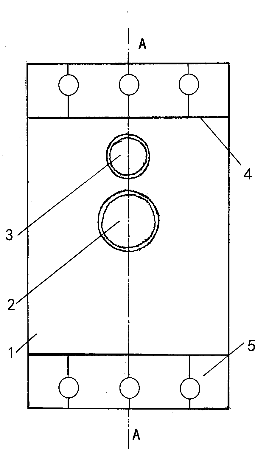
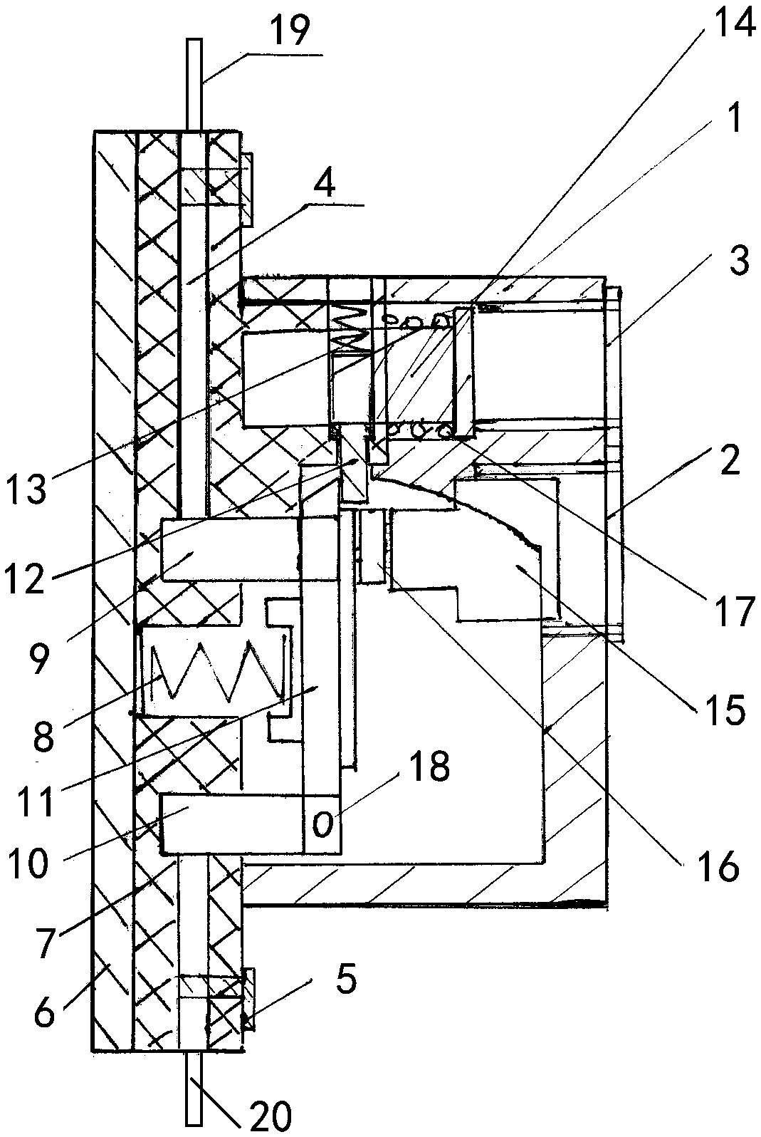
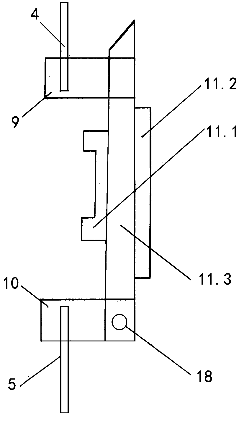
[0033] Embodiment 1, with reference to attached Figure 1-2 , a button-type high-voltage remote control switch for a power distribution box mentioned in the present invention, its technical solution is: including an insulating shell 1, an access button installer 2, a circuit breaker button installer 3, a power supply terminal 5, and an electric terminal 5. Installation base plate 6, switch carrier 7, circuit disconnection spring 8, circuit disconnection movable knife edge 9, circuit disconnection fixed knife edge 10, opening and closing guillotine knife 11, circuit closing pin 12, circuit closing spring 13, circuit disconnecting actuator 14, circuit closing actuator 15, circuit return spring 17, fixed rotating shaft 18, switch carrier 7 is installed on one side of installation base plate 6, the upper side of switch carrier 7 is installed the power supply terminal 5 of external power supply line 19, and the lower side is installed Set the power terminal 5 of the external electr...

Embodiment 2

[0049] Embodiment 2, the difference between the present invention and embodiment 1 is:

[0050] Refer to attached Figure 13 , the access button installer 2 and the disconnect button installer 3 both use pneumatic remote buttons, including button cylinder b1, press down piston b2, gas pipeline b3, pneumatic reversing valve b4, and the inner cavity of the button cylinder b1 is provided with a lower Press the piston b2, the outside of the button cylinder b1 is connected to the remote pneumatic reversing valve b4 through the air pipeline b3, the pneumatic reversing valve b4 is provided with a reversing handle, and the access button installer 2 and The on-off of the break button installer 3.

[0051] The difference between the using method of the embodiment of the present invention and the using method of embodiment 1 is:

[0052] Specifically, when the pneumatic remote control circuit breaker is used, the compressed gas enters the button cylinder b1 in the circuit breaker butto...

Embodiment 3

[0054] Embodiment 3, the difference between the present invention and embodiment 1 is:

[0055] Refer to attached Figure 14 , the access button installer 2 and the disconnection button installer 3 both use electric remote buttons, and the two have the same structure; Figure 13Taking the circuit breaker button installer 3 as an example, it includes a coil pressing sleeve a1, a coil fixing sleeve a2, a coil a3, a current limiting resistor a4, an external power supply a5, an armature a6, and an operation switch a7. There is a coil pressure sleeve a1 at the end, an armature a6 is provided in the inner cavity of the coil fixing sleeve a2, and a coil a3 is provided outside the armature a6, and is connected to the operation switch a7, the current limiting resistor a4 and the external power supply a5 through wires to form a remote electric circuit. Control operation on and off.

[0056] The difference between the using method of the embodiment of the present invention and the usin...


PUM


Abstract

The invention relates to a button type high-voltage remote control switch for a distribution box. The technical scheme is as follows: the upper end of an opening and closing knife switch is matched with a circuit breaking and closing movable knife edge; the inner side of the opening and closing knife switch is provided with a circuit breaking spring for pushing the opening and closing knife switchaway from the circuit breaking and closing movable knife edge to realize circuit breaking, and the outer side of the upper end of the opening and closing knife switch is provided with a circuit closing actuator for pushing the opening and closing knife switch to the circuit breaking and closing movable knife edge to realize circuit conducting; the upper end of the opening and closing knife switchis matched and locked with a circuit closing pin, the circuit closing pin is moved upwards by the pressing and pushing of a circuit breaking actuator, and the opening and closing knife switch is enabled to be opened to realize circuit breaking; and the outer side of the circuit breaking actuator is provided with a circuit breaking button installer, and the outer side of the circuit closing actuator is provided with a circuit conducting button installer. The beneficial effects are that the external remote control structure can be simplified through designing the button type structure, the diversity can be realized, the structure is simple, the occupied area is small, the safety factor is greatly improved, and the fault rate is significantly reduced.

Description

technical field [0001] The invention relates to a high-voltage control switch and a method, in particular to a push-button high-voltage remote control switch for a distribution box. Background technique [0002] Electricity is the driving force of modern industry. In the process of electric power transmission, high voltage changes to low voltage is a common situation encountered by industrial and mining units. At present, the operation of changing high voltage to low voltage on the distribution box is mostly manual operation. The process is: one person operates, and two or more people monitor. This is an important safety measure written into the operating procedures, otherwise It is not allowed to operate. In this way, the operation is not only troublesome, but also the operators and guardians will be disturbed by the electromagnetic field, which will affect the physical and mental health. [0003] Therefore, it is absolutely necessary to use remote operation. The existing ...

Claims


Application Information

Patent Timeline
Patent Type & Authority Applications(China)
IPC IPC(8): H01H9/02H01H21/54H01H71/58H01H3/24
CPCH01H3/24H01H9/02H01H21/54H01H71/58H02B1/04H02B1/205H02B3/00
Inventor 秘天昊秘杰云程强
Owner 上海兰慧电器设备有限公司
Why Eureka
Eureka Blog
Learn More