
Cooking device

A technology for cooking equipment and pots, which is applied in the field of kitchen utensils, can solve problems such as short boards and reduce heat transfer efficiency, and achieve the effects of uniform temperature, reduced heat transfer efficiency, and improved heat preservation.

Active Publication Date: 2019-11-19
FOSHAN SHUNDE MIDEA ELECTRICAL HEATING APPLIANCES MFG CO LTD
View PDF10 Cites 4 Cited by
  • Summary
  • Abstract
  • Description
  • Claims
  • Application Information

AI Technical Summary

Problems solved by technology

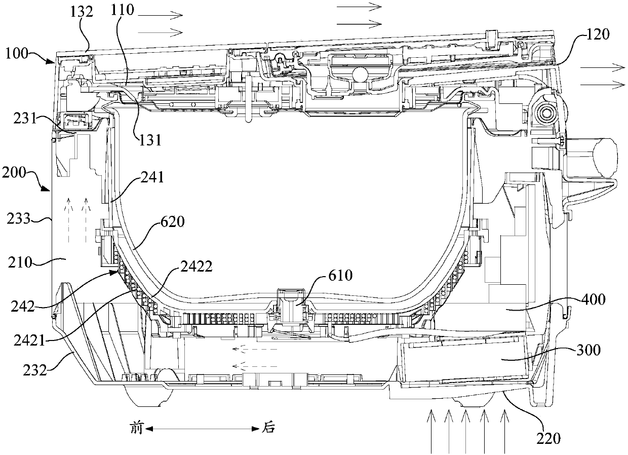
[0005] In the cooking equipment provided by the above-mentioned embodiments of the present invention, the inner cavity of the upper cover and the inner cavity of the pot can be connected by a ventilation structure to form a connected air duct, so that the fan runs and drives the airflow to cool and dissipate the electronic components in the inner cavity of the pot. , the high-temperature airflow formed in the inner cavity of the pot is driven to the ventilation structure and can be sent into the inner cavity of the upper cover through the ventilation structure, so that the high-temperature airflow can heat and keep the upper cover in the process of flowing through the inner cavity of the upper cover. Among them, it can be understood that the heat transfer process is driven by the temperature difference. Here, the temperature difference between the upper cover and the inner pot in the body of the pot can be reduced to a certain extent by heating and keeping the upper cover, thereby reducing the pressure of the inner pot in the direction of the upper cover. The heat transfer efficiency is conducive to improving the thermal insulation of the inner pot, which solves the problem of the shortcoming of the cooking equipment in terms of energy efficiency improvement due to the poor thermal insulation of the inner pot, and is also conducive to the uniform temperature of the upper and lower surfaces of the food in the pot, improving the cooking taste. And in this structure, the heat used for heating and insulating the upper cover comes from the recovered heat of the electronic components, and there is no need to consume additional energy to heat the upper cover in a targeted manner, which realizes the optimal allocation of resources and the full utilization of energy It is helpful for cooking equipment to achieve first-class energy efficiency and realize energy saving and emission reduction of products

Method used


Image

  • Cooking device
  • Cooking device
  • Cooking device

Examples


Embodiment Construction

[0036] In order to understand the above-mentioned purpose, features and advantages of the present invention more clearly, the present invention will be further described in detail below in conjunction with the accompanying drawings and specific embodiments. It should be noted that, in the case of no conflict, the embodiments of the present application and the features in the embodiments can be combined with each other.

[0037] In the following description, many specific details are set forth in order to fully understand the present invention. However, the present invention can also be implemented in other ways different from those described here. Therefore, the protection scope of the present invention is not limited by the specific details disclosed below. EXAMPLE LIMITATIONS.

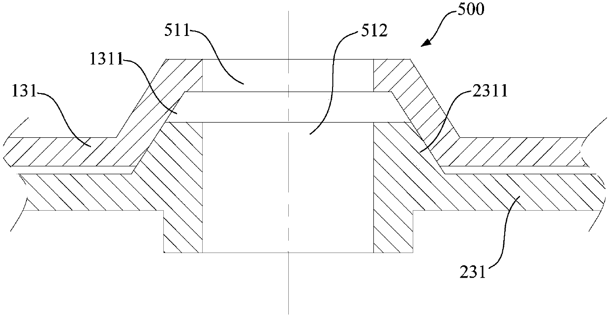
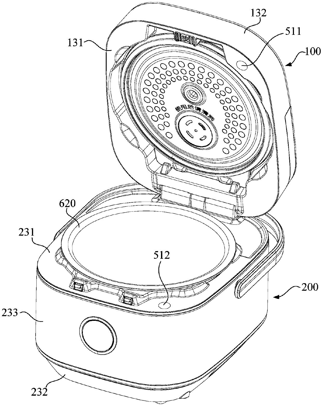
[0038] Refer below Figure 1 to Figure 3 A cooking device according to some embodiments of the present invention is described.

[0039] Such as Figure 1 to Figure 3 As shown, the cooking device p...


PUM


Abstract

The invention provides a cooking device. The cooking device comprises an upper cover provided with an upper cover inner cavity and an exhaust port for exhausting air from the upper cover inner cavity;a pot body provided with a pot body inner cavity and an air inlet for allowing air to enter the pot body inner cavity; a ventilation structure used for communicating the pot body inner cavity with the upper cover inner cavity; a fan arranged in the pot body inner cavity, wherein during the running process of the fan, the fan drives the airflow to enter the pot body inner cavity from the air inlet, and the airflow in the pot body inner cavity is driven to be exhausted from the ventilation structure; and an electronic element arranged in the pot body inner cavity. The airflow flowing from the air inlet to the ventilation structure in the pot body inner cavity can dissipate the heat of the electronic element. According to the cooking equipment, the heat dissipating capacity of the electronicelement in the pot body is recycled to heat the upper cover, so that the heat transfer efficiency of the inner pot in the direction of the upper cover is reduced. The heat preservation performance ofthe inner pot is improved. No extra energy is consumed to heat the upper cover in a targeted mode. The optimal configuration of resources and the sufficiency of energy utilization are achieved. The cooking equipment can achieve first-level energy efficiency.

Description

technical field [0001] The present invention relates to the field of kitchen utensils, in particular to cooking equipment. Background technique [0002] In the process of realizing the present invention, the inventor found that the prior art has the following technical problems: existing cooking equipment such as electric cookers generally have low energy efficiency, resulting in a serious waste of resources, specifically, IH electric cookers, which pass coils The high-frequency magnetic field generated by the coil of the disk heats the metal liner, but at the same time, the electronic components such as the coil and the IGBT that generate the high-frequency magnetic field will generate high heat when they work, and the heat of these electronic components must be dissipated in time, otherwise the electronic components will be damaged. It will burn out due to high temperature. Therefore, the IH rice cooker and other cooking equipment will be equipped with cooling fans. The a...

Claims


Application Information

Patent Timeline
Patent Type & Authority Applications(China)
IPC IPC(8): A47J27/00A47J27/086A47J36/24
CPCA47J27/004A47J27/086
Inventor 邢胜华刘化勇梁志佳马利吴慧民罗飞龙黄韦铭羊小亮瞿月红
Owner FOSHAN SHUNDE MIDEA ELECTRICAL HEATING APPLIANCES MFG CO LTD
Learn More