Heat exchanger, method of manufacturing a heat exchanger and air conditioner with the heat exchanger

A technology for heat exchangers and manufacturing methods, applied to heat exchange equipment, manufacturing tools, refrigerators, etc., can solve the problems of rising manufacturing costs, deformation of plate-shaped heat sinks, and enlarging heat exchangers, and achieve the effect of easy manufacturing

Inactive Publication Date: 2010-07-07
MITSUBISHI ELECTRIC CORP
View PDF2 Cites 35 Cited by
  • Summary
  • Abstract
  • Description
  • Claims
  • Application Information

AI Technical Summary

Problems solved by technology

[0006] According to the technology described in Patent Document 1, the fin pitch is large, and there is a problem that the heat exchanger needs to be enlarged in order to obtain a predetermined heat exchange performance.
[0007] In addition, although the heat exchanger described in Patent Document 2 has high heat exchanging performance, since the flat heat exchange tubes are brazed to the plate-shaped fins at high temperature, it is necessary to carry out heat transfer for the plate-shaped fins after molding the heat exchanger. Hydrophilic treatment, in this way, th

Method used


Image

  • Heat exchanger, method of manufacturing a heat exchanger and air conditioner with the heat exchanger
  • Heat exchanger, method of manufacturing a heat exchanger and air conditioner with the heat exchanger
  • Heat exchanger, method of manufacturing a heat exchanger and air conditioner with the heat exchanger

Examples


no. 1 approach

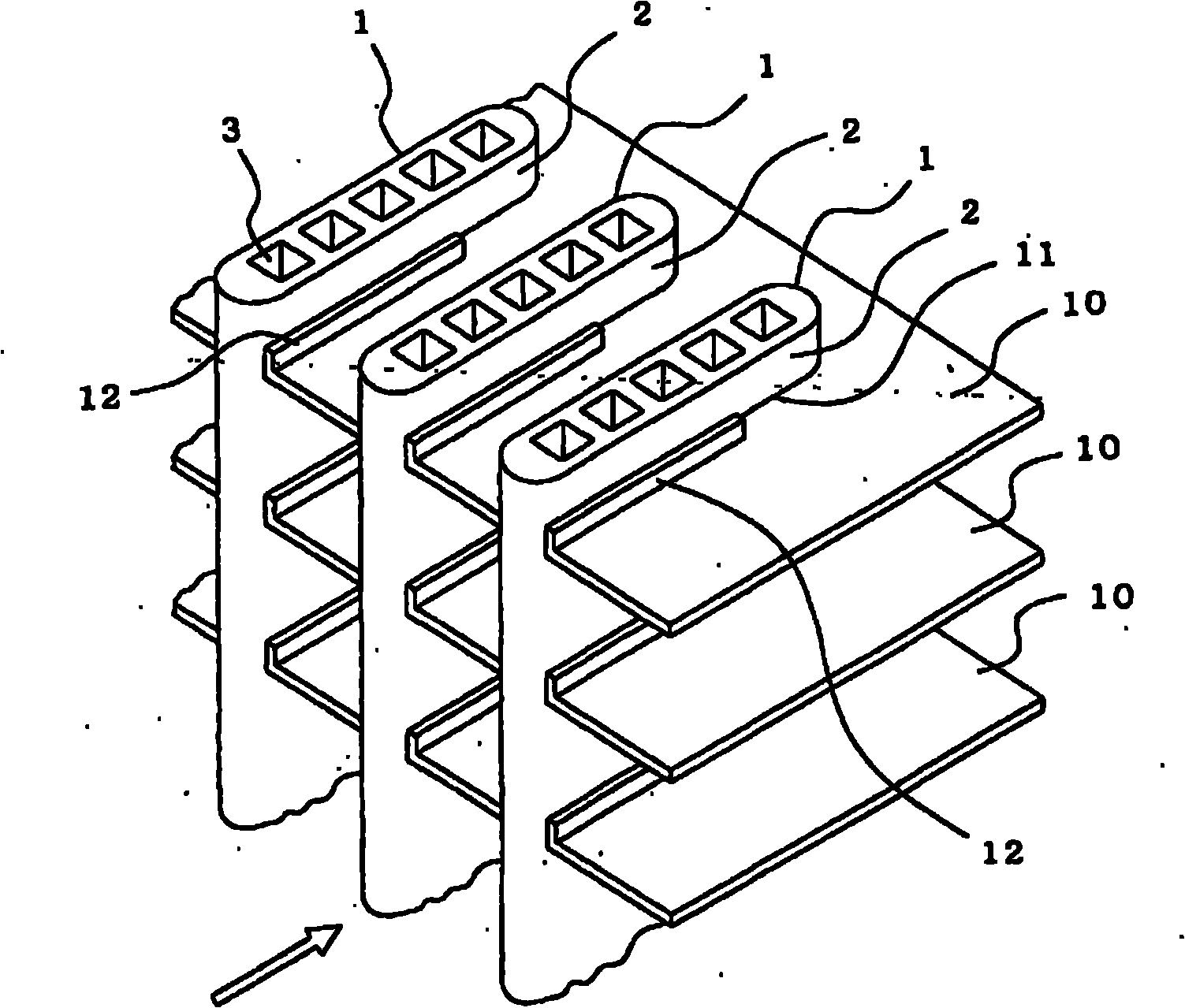
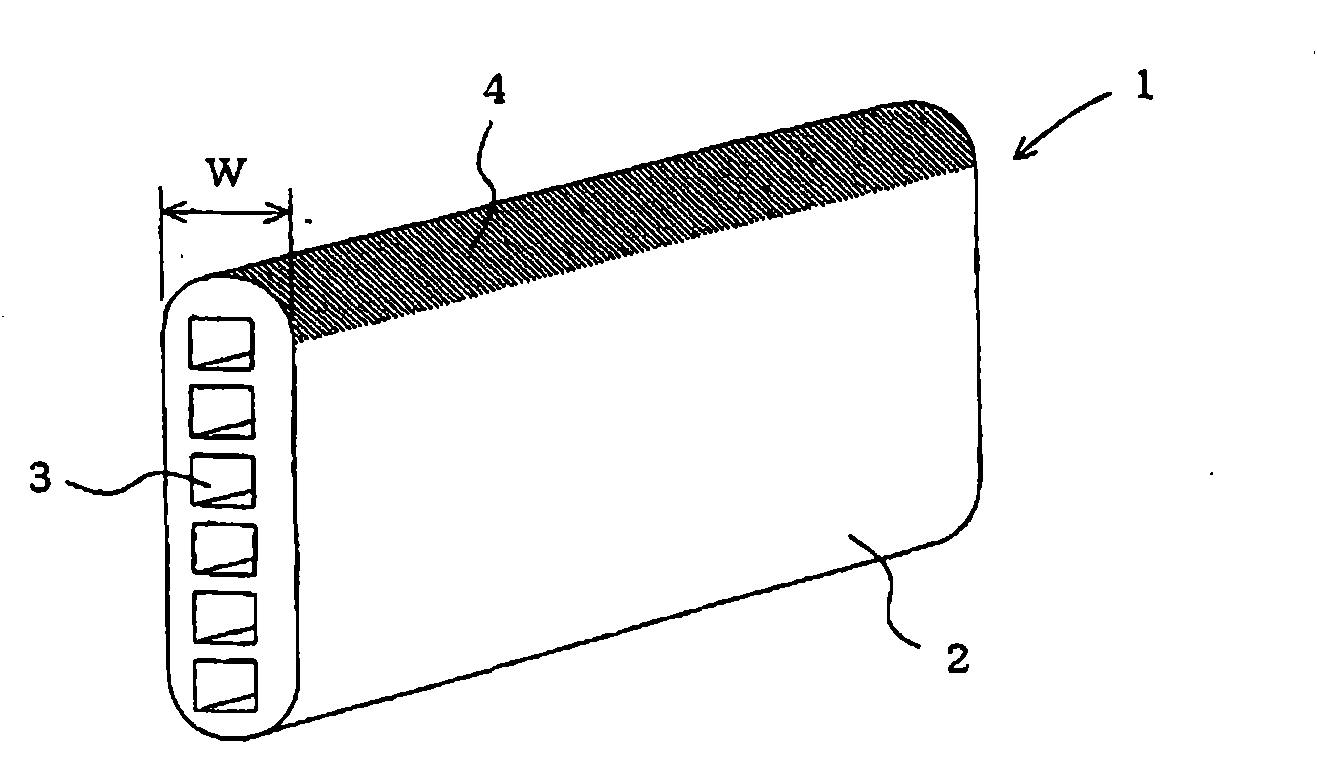
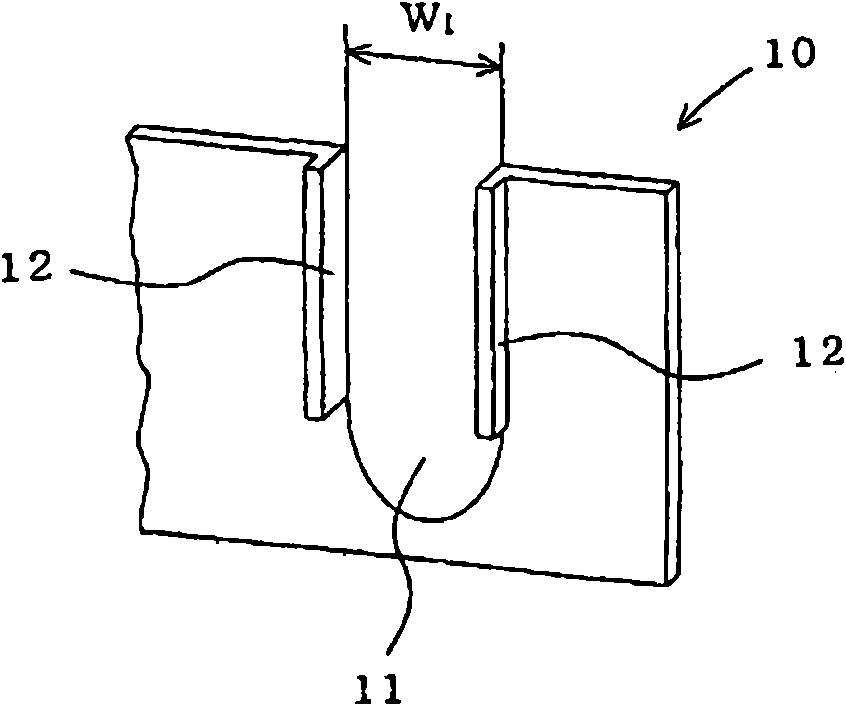
[0024] figure 1 It is an explanatory diagram of main parts of the heat exchanger according to the first embodiment of the present invention, figure 2 for figure 1 An explanatory diagram of the heat transfer tube, image 3 for figure 1 An explanatory diagram of the main part of the plate heat sink. In addition, for ease of description, parts of the drawings are enlarged and shown.

[0025] In the drawings, reference numeral 1 is a heat transfer tube formed of flat tubes 2 provided with a refrigerant flow path 3, and reference numeral 10 is a heat transfer tube 1 stacked at a predetermined interval, with air interposed therebetween. Flowing plate heat sink.

[0026] The heat transfer tube 1 is provided with a plurality of refrigerant passages 3 arranged in the longitudinal direction of the flat tube 2 formed of aluminum alloy and extending in the longitudinal direction. A layer of low melting point solder 4 (hereinafter also referred to as solder layer 4 ) is provided on ...

no. 2 approach

[0037] In this embodiment, in an air conditioner having a refrigeration cycle in which a compressor, a condenser, an expansion valve, and an evaporator are sequentially connected by refrigerant piping, the method of the first embodiment is adopted for both or either one of the condenser and the evaporator. heat exchanger.

[0038] According to this embodiment, a space-saving and highly reliable air conditioner can be obtained.


PUM

PropertyMeasurementUnit
Melting pointaaaaaaaaaa
Thicknessaaaaaaaaaa
Heat resistance temperatureaaaaaaaaaa

Abstract

The present invention provides a heat exchanger, which is improved in terms of heat transfer efficiency and space saving, which can be manufactured with simplified steps and at a reduced cost, and which ensures improved reliability when used, a method for manufacturing the heat exchanger, and an air conditioner including the heat exchanger. The heat exchanger includes: a plurality of plate fins, made of an aluminum alloy, subjected to a hydrophilic film forming treatment, and stacked at predetermined intervals to allow air to flow therebetween; and a flat heat transmission tube, made of an aluminum alloy and provided with a plurality of refrigerant flow paths arranged in a major axis direction of the tube so as to extend in a longitudinal direction of the tube; wherein the heat transmission tube is fitted into grooves provided in the plate fins, and a solder layer provided on an outer surface of the heat transmission tube at a front edge thereof is melted such that the heat transmission tube is fixedly secured to the plate fins by the solder.

Description

technical field [0001] The present invention relates to a heat exchanger composed of plate fins and heat transfer tubes, a manufacturing method thereof, and an air conditioner equipped with the heat exchanger, wherein the plate fins are stacked at predetermined intervals so that air flows between them. The heat transfer tubes are formed of flat tubes provided with a plurality of refrigerant flow paths and incorporated into plate-shaped fins. Background technique [0002] In the conventional manufacturing method of heat exchangers using flat tubes made of aluminum alloy, the flat tubes are welded to the flat tubes with aluminum alloy brazing filler metal to prevent the flat tubes from not joining the corrugated fins during the brazing process. (For example, refer to Patent Document 1). [0003] In addition, there is also a method of manufacturing a heat exchanger in which, on the surface of a flat heat exchange tube formed by extrusion of aluminum alloy, forming The formed ...

Claims


Application Information

Patent Timeline
IPC IPC(8): F28D1/053F28F1/30F28F21/08F24F1/00F25B39/00B23K1/00B23K1/20B23K1/008F28F1/32
CPCF28F1/32B23K1/0012F28F21/084F28D1/05383F28F21/089B21D53/08F28F2245/02B23K2201/14F28F2215/12B23K2101/14
Inventor 森秀树花木隆行早川满贞我妻正章
Owner MITSUBISHI ELECTRIC CORP
Why Eureka
Try Eureka