Heat Exchanger Comprising Wave-shaped Fins

a wave-shaped fin and heat exchanger technology, applied in the field of energy conversion, can solve the problems of high capital cost of these systems, thwarting commercialization, and increasing the capital cost of otec plants, so as to increase the overall convection heat transfer in the flow passage, increase the fluid back pressure, and enhance the effect of heat transfer

Inactive Publication Date: 2011-06-02
LOCKHEED MARTIN CORP
View PDF39 Cites 34 Cited by
  • Summary
  • Abstract
  • Description
  • Claims
  • Application Information

AI Technical Summary

Benefits of technology

[0016]An embodiment of the present invention comprises first conduits for conveying a first fluid through the heat exchanger and second conduits for conveying a second fluid through the heat exchanger, wherein the first fluid and second fluid are thermally coupled by the heat exchanger. The first conduits include flow passages that induce turbulence in the flowing first fluid without significantly increasing fluid back pressure. The turbulence is induced by wave-shaped fins that project into each first conduit to form a plurality of flow passages. The wave-shaped fins are continuous along the direction of fluid flow. Adjacent pairs of wave-shaped fins define three sections in each flow passage: first and second sections that are interposed by a third section. The wave-shape of the fins results in a continuous variation of the cross-sectional area of the third section along the direction of fluid flow. As this cross-sectional area changes, the first fluid flowing through the flow passage is forced to exchange between the third section and each of the two remaining sections of the flow passage. This exchange of fluid between the three sections induces a swirl, or vortex, flow in the first and second sections, which increases the overall convection heat transfer in the flow passage.
[0017]The fins are arranged within each first conduit such alternating fins project into the first conduit from opposite surfaces and so that the wave shapes of adjacent fin pairs are offset by a phase difference. This phase diffe

Problems solved by technology

The total energy available is one or two orders of magnitude higher than other ocean-energy options such as wave power, but the small magnitude of the temperature difference makes energy extraction comparatively difficult and expensive, due to low thermal efficiency.
This temperature difference generally increases with decreasing latitude (i.e., near the equator, in the tropics), but evaporation prevents the surface temperature from exceeding 27° C. Also, the subsurface water rarely falls below 5° C. Historically, the main technical challenge of OTEC was to generate significant amounts of power, efficiently, from this very small temperature ratio.
OTEC systems have been shown to be technically viable, but the high capital cost of these systems has thwarted commercialization.
Heat exchangers are the second largest contributor to OTEC plant capital cost (the largest is the cost of the offshore moored vessel or platform).
For OTEC systems, while there are many conventional heat-exchanger designs that can be considered, there are, as a practical matter, no good choices.
This drives the size and cost for this type of heat exchanger and reduces its economic viability.
Unfortunately, plate-fin heat exchangers are undesirable for many applications because of high material and fabrication costs.
Second, brazed joints are poorly suited to applications in which corrosive media are used.
In OTEC applications, brazed

Method used


Image

  • Heat Exchanger Comprising Wave-shaped Fins
  • Heat Exchanger Comprising Wave-shaped Fins
  • Heat Exchanger Comprising Wave-shaped Fins

Examples


Embodiment Construction

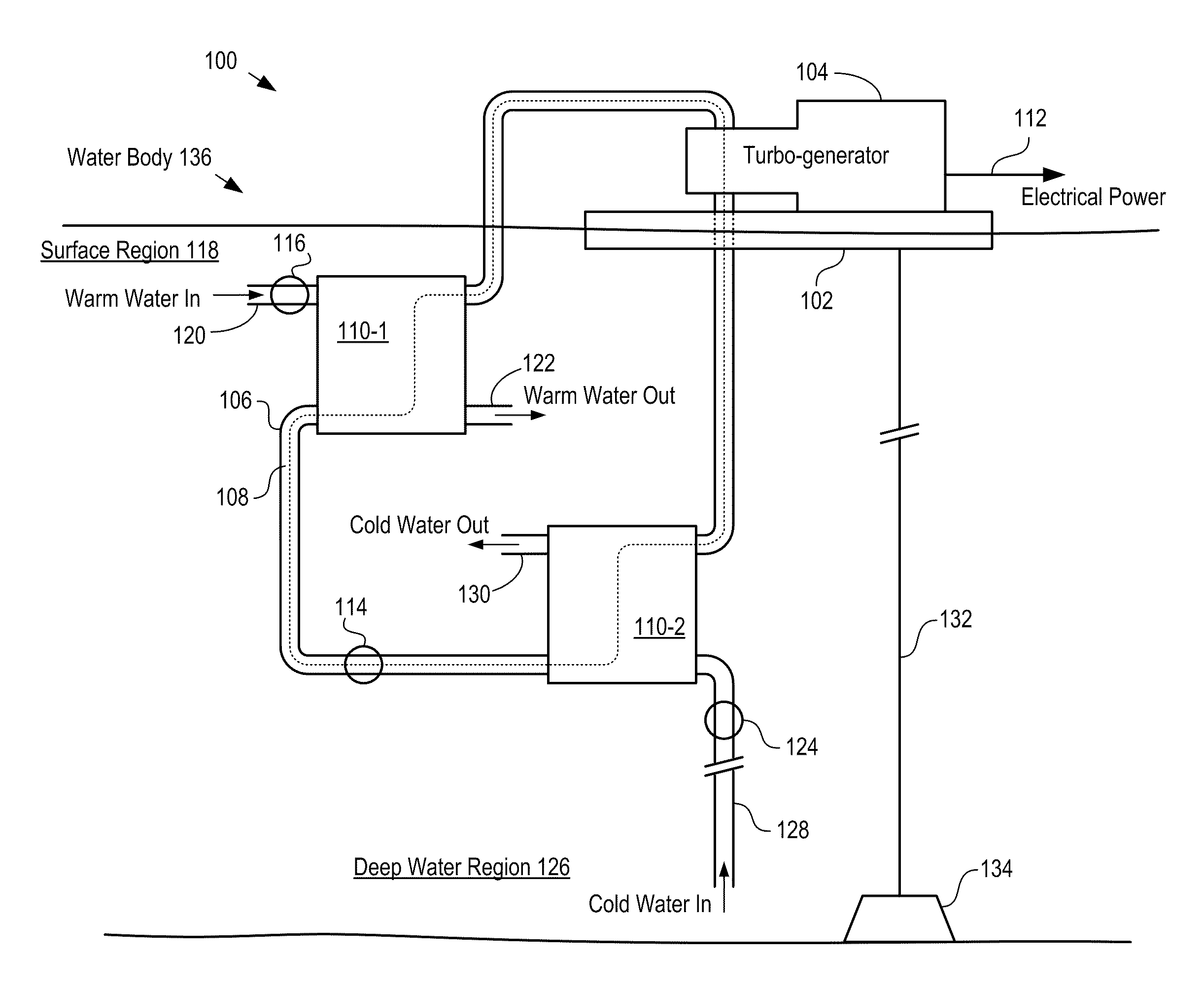
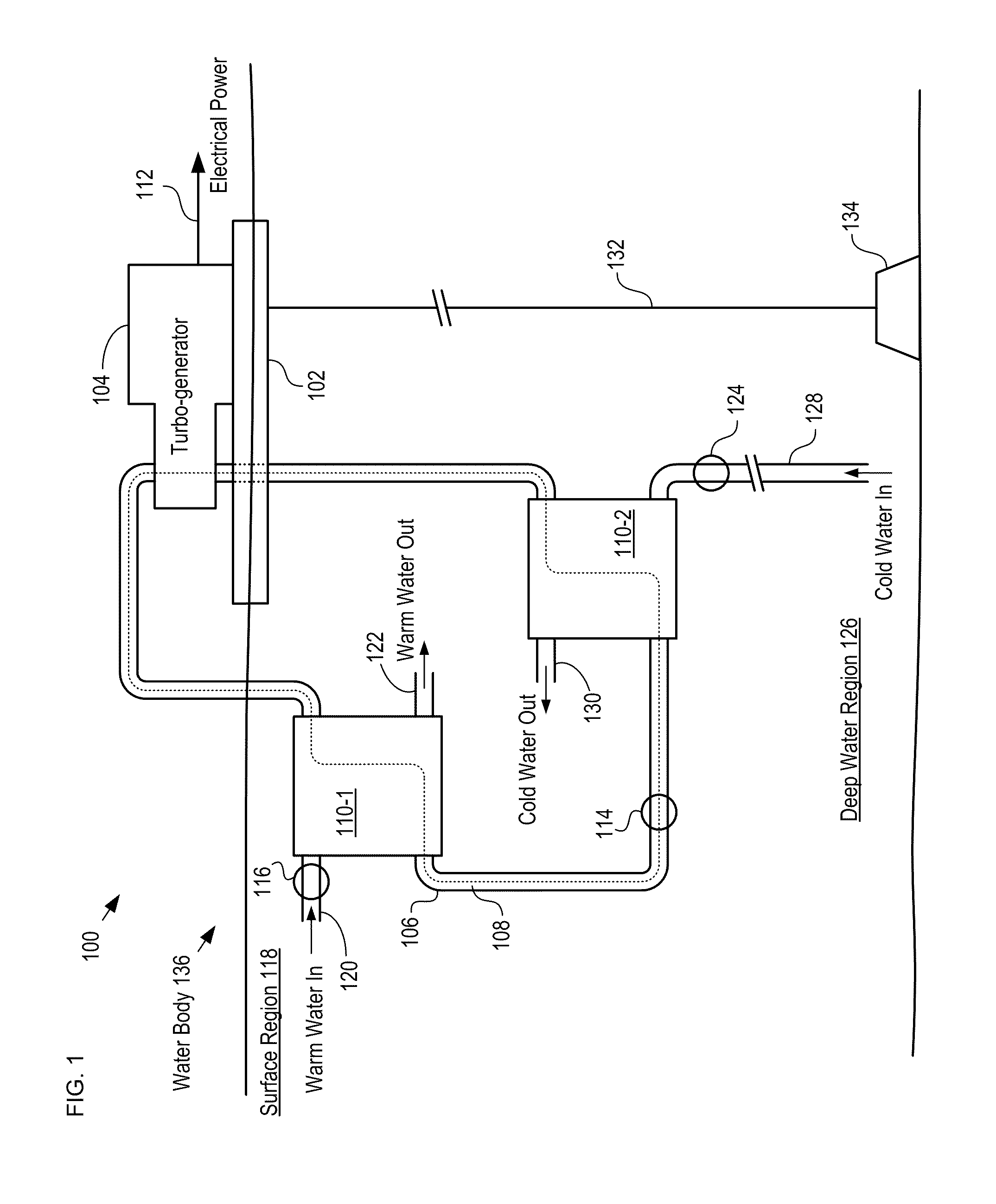
[0039]FIG. 1 depicts a schematic diagram of an OTEC power generation system in accordance with an illustrative embodiment of the present invention. OTEC system 100 comprises turbogenerator 104, closed-loop conduit 106, heat exchanger 110-1, heat exchanger 110-2, pumps 114, 116, and 124, and conduits 120, 122, 128, and 130. OTEC system 100 is deployed in water body 136 wherein a suitable temperature difference exists between water near the surface and water located at a deep level of water body 136.

[0040]Turbo-generator 104 is a conventional turbine-driven generator. Turbogenerator 104 is mounted on floating platform 102, which is a conventional floating energy-plant platform. Platform 102 is anchored to the ocean floor by mooring line 132 and anchor 134, which is embedded in the ocean floor. In some instances, platform 102 is not anchored to the ocean floor but is allowed to drift. Such a system is sometimes referred to as a “grazing plant.”

[0041]In typical operation, pump 114 pumps...


PUM


Abstract

A heat exchanger for exchanging heat between a first fluid and a second fluid is disclosed; wherein the heat exchanger has improved thermal efficiency and low fluid back pressure. The heat exchanger comprises conduits for conveying the first fluid, wherein the conduits include a plurality of flow passages. The flow passages are defined by a plurality of fins that are continuous along the direction of flow of the first fluid. Each fin includes a wave-shaped region, and adjacent fins sub-divide each flow passage into first and second sections that are interposed by a third section. The wave-shape of the fins creates a continuously varying cross-sectional area for each third section. The variation of the cross-sectional area of the third section, coupled with the wave-shape of the fins, induces a swirl flow between the third section and each of the first and second sections. This swirl flow improves the efficiency of the overall convection heat transfer in each conduit. Further, the overall cross-sectional area of each conduit remains constant even as the cross-sectional areas of individual flow passages changes, which mitigates the development of back pressure in the flow of the first fluid.

Description

FIELD OF THE INVENTION[0001]The present invention relates to energy conversion in general, and, more particularly, to heat exchangers.BACKGROUND OF THE INVENTION[0002]The Earth's oceans are continually heated by the sun and cover nearly 70% of the Earth's surface. The temperature difference between deep and shallow waters contains a vast amount of solar energy that can potentially be harnessed for human use. In fact, it is estimated that the thermal energy contained in the temperature difference between the warm ocean surface waters and deep cold waters within ±10° of the Equator represents a 3 Tera-watt (3×10¹² W) resource.[0003]The total energy available is one or two orders of magnitude higher than other ocean-energy options such as wave power, but the small magnitude of the temperature difference makes energy extraction comparatively difficult and expensive, due to low thermal efficiency.[0004]Ocean thermal energy conversion (“OTEC”) is a method for generating electricity which ...

Claims


Application Information

Patent Timeline
IPC IPC(8): F28F1/12F28F3/12F28F7/00
CPCF03G7/05F28D1/022F28D1/0477F28D7/1684F28D9/0062Y02E10/34F28F1/12F28F1/16F28F3/02F28F3/12F28D9/0081Y02E10/30
Inventor ELLER, MICHAEL R.BROWN, RANDY J.TAKESHITA, RIKI P.
Owner LOCKHEED MARTIN CORP
Why Eureka
Try Eureka