Special cooling dryer for vacuum nitrogen-filled insecticidal sterilization disinfection equipment

A technology of sterilization and refrigerating machine, which is applied to the separation of dispersed particles, chemical instruments and methods, filtration of dispersed particles, etc. Air filtration function, reasonable structure, and the effect of improving the efficiency of cooling and drying

Pending Publication Date: 2019-11-19
SHANGHAI HUIHAI VACUUM MASCH EQUIP CO LTD
View PDF0 Cites 3 Cited by
  • Summary
  • Abstract
  • Description
  • Claims
  • Application Information

AI Technical Summary

Problems solved by technology

[0002] Cold dryer is the abbreviation of refrigerated desiccant, which belongs to the air source processing components in the pneumatic system. It mainly includes four parts: refrigeration compressor, condenser, evaporator and thermal expansion valve. The compressed air is cooled to the range of 2 to 10 degrees Celsius to remove the moisture in the compressed air. The main body of the cold dryer generates heat during the working process. If the heat is not dissipated in time, it will affect the service life of the main body of the cold dryer, and even burn out the components and affect the use. In addition, there are impurities in the compressed air, and the impurities enter the body of the cold dryer and adhere to the tube wall, which affects the efficiency of cold drying. For this reason, we propose a special cold dryer for vacuum nitrogen-filled insecticide, sterilization and disinfection equipment

Method used


Image

  • Special cooling dryer for vacuum nitrogen-filled insecticidal sterilization disinfection equipment
  • Special cooling dryer for vacuum nitrogen-filled insecticidal sterilization disinfection equipment
  • Special cooling dryer for vacuum nitrogen-filled insecticidal sterilization disinfection equipment

Examples


Embodiment Construction

[0020] The following will clearly and completely describe the technical solutions in the embodiments of the present invention with reference to the accompanying drawings in the embodiments of the present invention. Obviously, the described embodiments are only some, not all, embodiments of the present invention. Based on the embodiments of the present invention, all other embodiments obtained by persons of ordinary skill in the art without making creative efforts belong to the protection scope of the present invention.

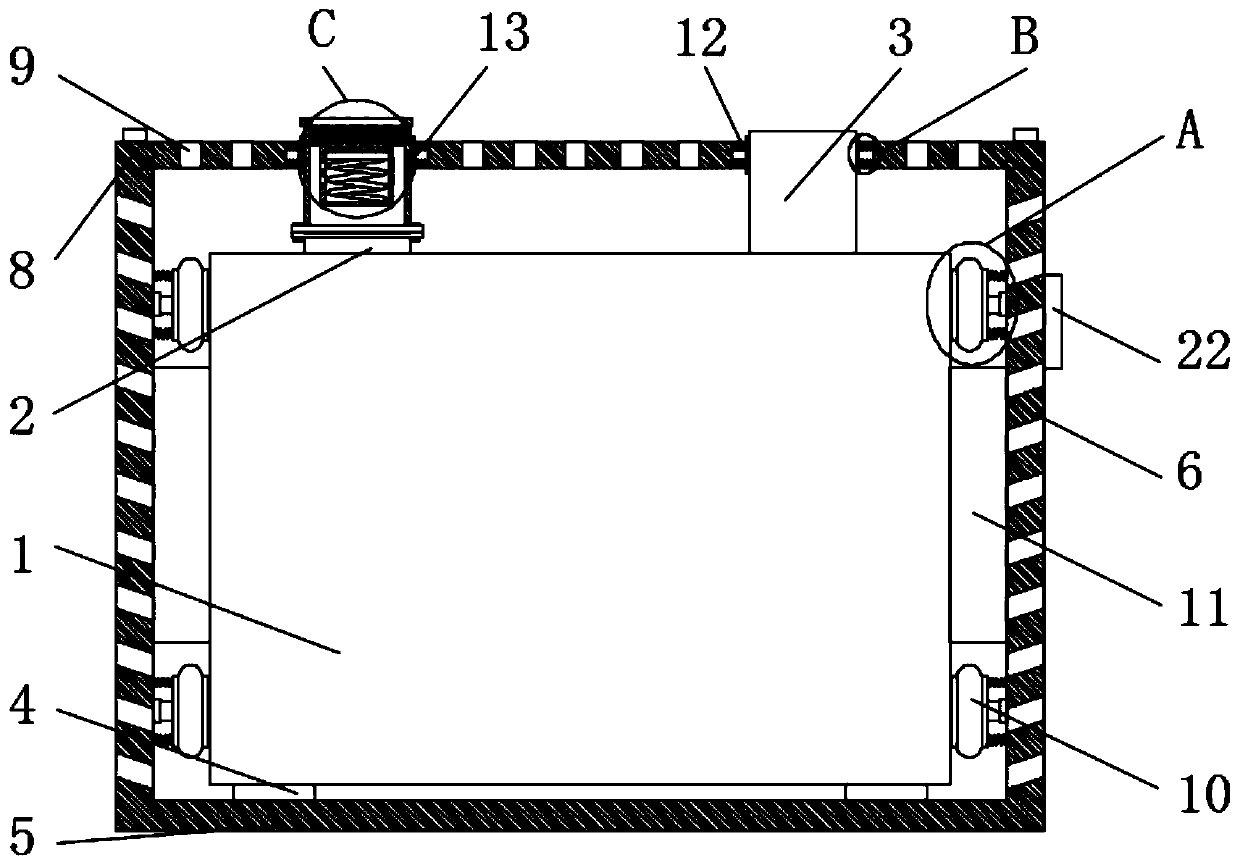
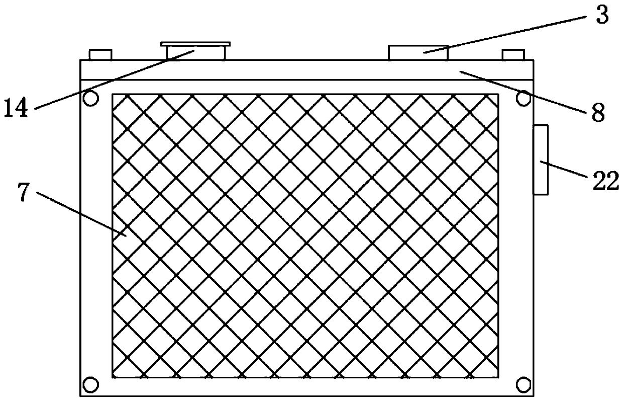
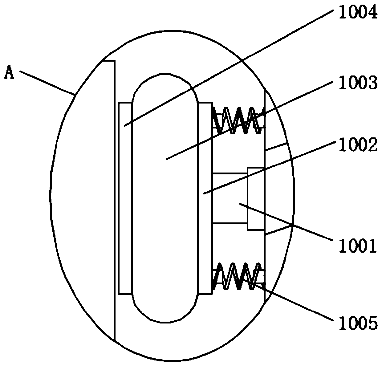
[0021] see Figure 1-5 , the present invention provides a technical solution: a special cold dryer for vacuum nitrogen-filled insecticide, sterilization and disinfection equipment, including a cold dryer body 1, an air inlet 2 is installed at one end of the cold dryer body, and the The other end of the cold dryer body is equipped with an air outlet 3, a cooling mechanism is installed on the shell of the cold dryer body, an air filter mechanism is installed on ...


PUM


Abstract

The invention discloses a special cooling dryer for vacuum nitrogen-filled insecticidal sterilization disinfection equipment. According to the special cooling dryer, the main structure of the specialcooling dryer comprises a cooling dryer body, an air filtering mechanism and a heat dissipation mechanism; compressed air is filtered by the air filtering mechanism to prevent the impurities in the air from entering the cooling dryer body so as to improve the cooling drying efficiency; the heat dissipation mechanism performs vibration reducing and heat dissipation on the cooling dryer body, wherein the cooling dryer body is clamped and fixed by a border through a vibration reducing mechanism, and a vibration reducing airbag, a first spring and a rubber rod are retractable structures, such thatthe vibration generated during the working of the cooling dryer body can be absorbed, and the cooling dryer body can be effectively protected; through a first venting hole and heat dissipation fans on the left side, the right side and the rear side, the cooling dryer body is subjected to multi-angle ventilation and heat dissipation, such that the heat of the cooling dryer body can be rapidly dissipated, and the service life of the cooling dryer body can be effectively protected; and through the threaded connection between a threaded filtering main shell body and an installing column, the installing column and an air filtering membrane can be conveniently removed and replaced.

Description

technical field [0001] The invention relates to the technical field of cold dryers, and the specific field is a special cold dryer for vacuum nitrogen-filled insecticide, sterilization and disinfection equipment. Background technique [0002] Cold dryer is the abbreviation of refrigerated desiccant, which belongs to the air source processing components in the pneumatic system. It mainly includes four parts: refrigeration compressor, condenser, evaporator and thermal expansion valve. The compressed air is cooled to the range of 2 to 10 degrees Celsius to remove the moisture in the compressed air. The main body of the cold dryer generates heat during the working process. If the heat is not dissipated in time, it will affect the service life of the main body of the cold dryer, and even burn out the components and affect the use. In addition, there are impurities in the compressed air, and the impurities enter the body of the cold dryer and adhere to the tube wall, which affects...

Claims


Application Information

Patent Timeline
Patent Type & Authority Applications(China)
IPC IPC(8): B01D53/26B01D46/10
CPCB01D46/10B01D53/265
Inventor 邵明官邵滔滔
Owner SHANGHAI HUIHAI VACUUM MASCH EQUIP CO LTD
Why Eureka
Try Eureka