Corrugated steel plate rolling punching machine

A corrugated steel plate and punching machine technology, applied in the field of punching machines, can solve the problems of difficult control of hole position accuracy, difficult quality assurance, slow efficiency, etc., and achieve the effects of simple structure, reduced process and high efficiency

Inactive Publication Date: 2019-11-19
NANJING LIANZHONG CONSTR ENG TECH
View PDF0 Cites 1 Cited by
  • Summary
  • Abstract
  • Description
  • Claims
  • Application Information

AI Technical Summary

Problems solved by technology

The bolt holes on the above-mentioned longitudinal flanges are generally drilled in the next process after forming waves or punched by a punching machine, which is very slow in efficiency, difficult in positioning, difficult to control the position accuracy of the holes, and difficult in quality assurance

Method used


Image

  • Corrugated steel plate rolling punching machine
  • Corrugated steel plate rolling punching machine

Examples


Embodiment Construction

[0015] The present invention will be further described below in conjunction with accompanying drawing.

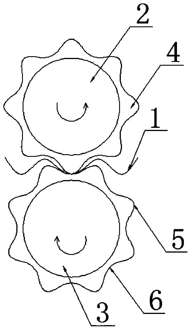
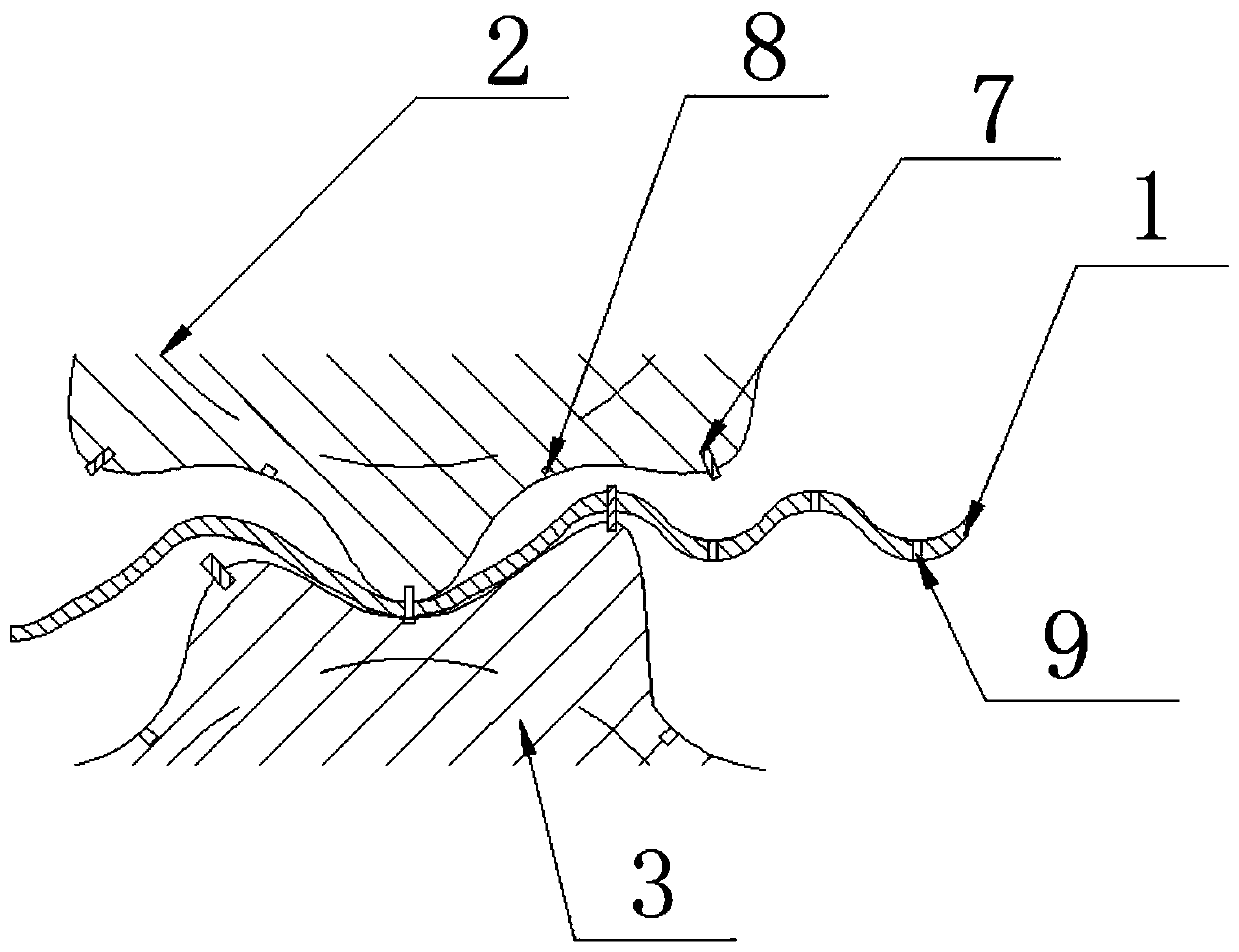
[0016] Such as figure 1 and figure 2 As shown, the present invention includes a corrugated steel plate 1, an upper roller shaft 2, a lower roller shaft 3, hobbing teeth 4, tooth crests 5, tooth valleys 6, punches 7, slots 8 and connection holes 9. Such as figure 1 As shown, two roller shafts, an upper roller shaft 2 and a lower roller shaft 3 , are arranged perpendicular to the advancing direction of the corrugated steel plate 1 . The two rollers are driven to rotate by a power mechanism such as a motor and a gear (not shown in the figure), and the directions of rotation are opposite. The upper roller 2 and the lower roller 3 are arranged up and down along the corrugated steel plate 1, and the axes of the two rollers Parallel, the plane formed by it is perpendicular to the plane of corrugated steel plate 1. The rotation directions of the two roller shafts are opposite,...


PUM


Abstract

The invention discloses a corrugated steel plate rolling punching machine. The corrugated steel plate rolling punching machine comprises a corrugated steel plate. Two roller shafts are arranged in thedirection perpendicular to the forwarding direction of the corrugated steel plate, the roller shafts are distributed along the upper side and the lower side of the corrugated steel plate, the axes ofthe roller shafts are parallel to each other and are located on the same vertical plane which is perpendicular to the plane where the corrugated steel plate is located, rolling teeth are arranged onthe peripheries of the roller shafts, the rolling teeth comprise tooth tops and tooth valleys, punching pins or hole slots are formed on the tooth tops and tooth valleys at the two ends of the upper rolling shaft and the lower rolling shaft respectively, and the punching pins and the hole slots are distributed on the tooth tops and the tooth valleys of the rolling teeth in a spaced mode, wherein the punching pins of the upper rolling teeth correspond to the hole slots of the lower rolling teeth, and the hole slots of the upper rolling teeth correspond to the punching heads of the lower rollingteeth. The corrugated steel plate rolling punching machine is simple in structure and high in efficiency, work procedures are reduced, and operation time is saved; and the formed hole position precision is high, and splicing of all sheet bars in a later stage is facilitated.

Description

technical field [0001] The invention relates to a punching machine, in particular to a rolling punching machine for corrugated steel plates. Background technique [0002] The applicant has been committed to the research and application of underground steel structure pipelines, and has applied for a box-shaped steel structure pipeline, which is composed of four corrugated steel plates with upper, lower, left and right outer arches to form a box-shaped steel pipeline. The connection between the circumferential direction plate and the plate of the single-section pipe is formed by bending the corrugated steel plate at the end perpendicular to the direction of the corrugated lines to form a longitudinal corrugated flange. The corrugated flange is provided with bolt holes. Flanges and bolts connect the four upper, lower, left, and right plates in the circumferential direction to form a single-section pipeline. The bolt holes on the above-mentioned longitudinal flanges are general...

Claims


Application Information

Patent Timeline
IPC IPC(8): B21D35/00
CPCB21D35/001
Inventor 战福军
Owner NANJING LIANZHONG CONSTR ENG TECH
Why Eureka
Try Eureka