Lower-limb exoskeleton robot with four-connecting-rod knee joints

An exoskeleton robot, knee joint technology, applied in manipulators, program-controlled manipulators, joints, etc., can solve the problems of poor bionic characteristics and motion performance, complex length adjustment device structure, and high cost, and achieve the effect of improving wearability.

Inactive Publication Date: 2019-11-19
SHANDONG ACAD OF SCI INST OF AUTOMATION
View PDF5 Cites 25 Cited by
  • Summary
  • Abstract
  • Description
  • Claims
  • Application Information

AI Technical Summary

Problems solved by technology

[0004] Existing exoskeleton robots generally design the knee joint as two connecting rods hinged, and the rotation center is fixed, but the instantaneous rotation center of the knee joint moves in a "J"-shaped curve when the human body moves. Therefore, this design is different from The joints of the human body are quite different, and the bionic characteristics and sports performance are relatively poor
[0005] Secondly, the existing exoskeleton robots generally only drive the hip joint and knee joint, and adopt a passive design for the ankle joint. This design cannot effectively support the ankle joint and has little effect on the wearer with an ankle joint injury.
[0006] In addition, the existing exoskeleton robot length adjustment device has a complex structure and high cost, and at the same time increases the control complexity of the exoskeleton robot

Method used


Image

  • Lower-limb exoskeleton robot with four-connecting-rod knee joints
  • Lower-limb exoskeleton robot with four-connecting-rod knee joints
  • Lower-limb exoskeleton robot with four-connecting-rod knee joints

Examples


Embodiment 1

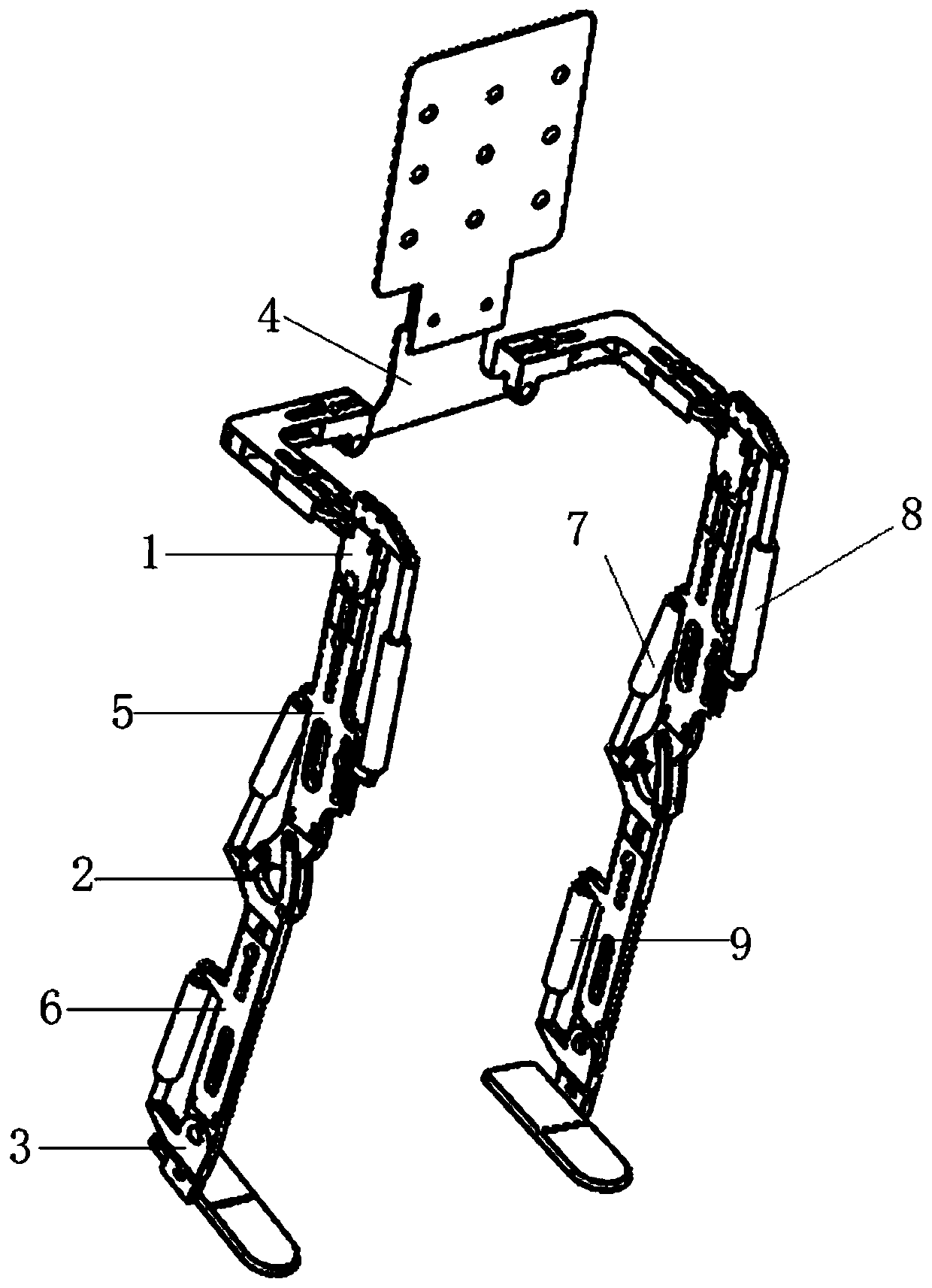
[0042] In one or more embodiments, a lower limb exoskeleton robot with a four-link knee joint is disclosed, such as figure 1 As shown, it includes: hip joint 1, knee joint 2, ankle joint 3, waist connecting part 4, thigh supporting part 5 and calf supporting part 6; wherein, hip joint 1 is connected with knee joint 2 through thigh supporting part 5, and knee joint 2 is connected to the ankle joint 3 through the calf support 6, and the left and right hip joints 1 are connected through the waist connection 4; the hip joint 1 is provided with a second drive device 8 for driving the thigh support 5, and the knee joint 2 is provided with a drive The first driving device 7 of the calf support 6 is provided with a third driving device 9 for driving the ankle joint 3 on the calf support 6, and the positions of the above driving devices can be adjusted according to actual needs.

[0043] Such as Figure 5As shown, the waist connector 4 includes a back resting plate 401, an upper hinge...


PUM


Abstract

The invention discloses a lower-limb exoskeleton robot with four-connecting-rod knee joints. The lower-limb exoskeleton robot comprises hip joints, the knee joints and ankle joints; one ends of the hip joints are connected with waist connecting pieces, the other ends of the hip joints are connected with the knee joints through thigh supporting pieces, and the hip joints are connected with the ankle joints through shank supporting pieces; the knee joints comprise knee joint upper supporting blocks, knee joint lower supporting blocks, first knee joint swing plates and second knee joint swing plates; the knee joint upper supporting blocks and the knee joint lower supporting blocks are hinged through the first knee joint swing plates and the second knee joint swing plates correspondingly to form four-connecting-rod structures; and first sliding grooves used for adjusting the length of the shank supporting pieces are formed in the knee joint lower supporting blocks. The ankle joints of lower-limb exoskeletons are in active linear driving and passive auxiliary mechanism modes, the auxiliary supporting capacity to the ankle joints is effectively improved, and a wearer can be helped to walk more conveniently.

Description

technical field [0001] The invention relates to the technical field of assisting and medical rehabilitation training robots, in particular to a four-link knee joint lower limb exoskeleton robot. Background technique [0002] The statements in this section merely provide background information related to the present invention and do not necessarily constitute prior art. [0003] The lower extremity exoskeleton is a kind of power-assisted device worn on the outside of the user's body. It provides power to the joints of the lower extremities through motors and hydraulic pumps, and transmits the gravity of the man-machine system to the ground through the mechanical legs of the exoskeleton, allowing the wearer to walk, etc. The lower limb movement provides functions such as power assistance and protective support. It integrates key technologies such as sensing, signal acquisition, gait recognition, and motion control, enabling the exoskeleton to help the wearer complete functions...

Claims


Application Information

Patent Timeline
Patent Type & Authority Applications(China)
IPC IPC(8): B25J9/00B25J17/00
CPCB25J9/0006B25J17/00
Inventor 肖永飞纪翔镜赵杰
Owner SHANDONG ACAD OF SCI INST OF AUTOMATION
Why Eureka
Try Eureka