
A local heat treatment device adapted to rapid repair in the field

A local heat treatment and rapid technology, applied in heat treatment furnaces, heat treatment equipment, fluid heaters, etc., can solve the problems of inconvenient movement, difficult to adjust the temperature in real time, difficult to transfer, etc., and achieve the effect of efficient, uniform, efficient and convenient heat treatment.

Active Publication Date: 2021-06-08
CHENGDU AIRCRAFT INDUSTRY GROUP
View PDF5 Cites 0 Cited by
  • Summary
  • Abstract
  • Description
  • Claims
  • Application Information

AI Technical Summary

Problems solved by technology

[0003] At present, most of the domestic thermal surface treatment processes are based on the factory building system, which is used to heat treat the surface of batch products or complete machines. The operating temperature ranges from 50 to 85°C. It is large in size, high in power consumption, low in precision, and difficult to transfer.
Once the surface of the equipment is damaged, it is generally returned to the factory for repair or emergency treatment. The long treatment period or poor treatment effect greatly reduces the efficiency of equipment use, especially for some special long-term use equipment and equipment with combat readiness. influences
And for the surface heat treatment of field equipment, because the field equipment is greatly affected by the external temperature, the traditional heat treatment equipment heats the air in a single form, and it is difficult to adjust the actual heat treatment temperature in real time according to the real-time changing external temperature
[0004] Therefore, in view of the defects of inconvenient movement, high power consumption, difficulty in applying surface heat treatment of field equipment, and single heat treatment form in the existing heat treatment equipment, the present invention discloses a local heat treatment device suitable for rapid repair in the field

Method used


Image

  • A local heat treatment device adapted to rapid repair in the field
  • A local heat treatment device adapted to rapid repair in the field
  • A local heat treatment device adapted to rapid repair in the field

Examples


Embodiment 1

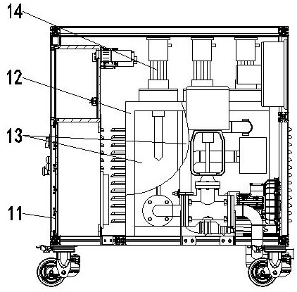
[0042] In this embodiment, a local heat treatment device adapted to rapid repair in the external field, such as figure 1 As shown, the air heater assembly 1 is included, and the air heater assembly 1 includes a box body 111 with an air inlet and an air outlet. The inside of the box body 111 is provided with an explosion-proof heating air bag 12, and the heating air bag The air inlet end of 12 is connected with the air inlet of box body 11 through fan, and the air outlet end of heating air bag 12 is connected with the air outlet of box body; The inside of described explosion-proof heating air bag 12 is divided into several sections and communicates with each other in turn along the direction of air flow. Each heating package section 13 is matched with an explosion-proof heater 14 for heating the air inside the heating package section 13 .

[0043] Both ends of the bottom of the box body 111 are respectively provided with fixed casters and swivel casters, and the convenient and ...

Embodiment 2

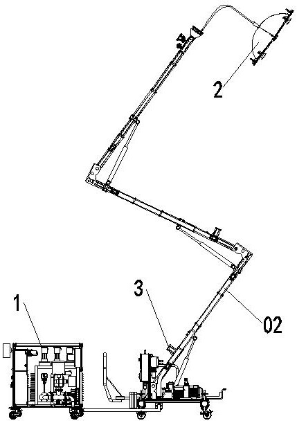
[0046] This embodiment is further optimized on the basis of embodiment 1, such as figure 2 As shown, it also includes a windshield assembly 2 and a pipe lifting assembly 3, the air inlet end of the windshield assembly 2 communicates with the air outlet of the box body 11 through the ventilation duct 02, and the air outlet end of the windshield assembly 2 is connected to the The heat treatment surface is bonded; the pipe lifting assembly 3 is arranged between the air heater assembly 1 and the wind shield assembly 2 and is used to lift the ventilation pipe 02 .

[0047] The wind cover assembly 2 is a cover structure with an air inlet end and an air outlet end. The air outlet end of the wind cover assembly 2 is bonded to the heat treatment surface to form a relatively airtight heating area. The air inlet end of the wind cover assembly 2 passes through the ventilation duct 02 is connected to the air outlet of the box body 111, the ventilation duct 02 is a retractable duct, and th...

Embodiment 3

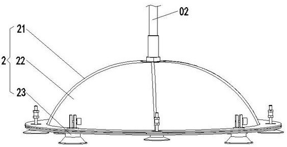
[0052] This embodiment is further optimized on the basis of above-mentioned embodiment 1 or 2, such as figure 2 and image 3 As shown, the windshield assembly 2 includes a carbon fiber skeleton 21, an insulating material layer 22, and a combined suction cup 23. The carbon fiber skeleton 21 and the insulating material layer 22 form a cover structure, and the end of the cover structure away from the heat treatment surface passes through The joint is connected to the air outlet end of the ventilation duct 02, and the end of the cover structure close to the heat treatment surface is evenly provided along the edge with several combined suction cups 23 for absorbing close to the heat treatment surface.

[0053] The carbon fiber skeleton 21 is arranged in an umbrella shape or a square frame shape, and the carbon fiber skeleton 21 is arranged in an umbrella shape, which can be conveniently folded and unfolded. When the windshield assembly 2 is not in use, the carbon fiber frame 21 i...


PUM


Abstract

The invention discloses a local heat treatment device adapted to rapid repair in the field, which includes an air heater assembly, a wind cover assembly, and a pipe lifting assembly assembled with each other. The air heater assembly includes a box body with an air inlet and an air outlet. The inside of the body is equipped with an explosion-proof heating air bag. The inlet end of the heating air bag is connected to the air inlet of the box through the fan, and the outlet end of the heating air bag is connected to the air outlet of the box. The inside of the explosion-proof heating air bag is along the direction of air flow. It is divided into several interconnected heating sections in turn, and each heating section is matched with an explosion-proof heater for heating the air inside the heating section; the wind cover assembly is used to absorb the heat treatment surface, and the lifting assembly is used for lifting Ventilation duct; the invention has the beneficial effects of high air heating efficiency, adaptability to surface heat treatment in complex areas of the field, little influence from the external environment, real-time control of airflow parameters, small device size, and flexible and convenient use.

Description

technical field [0001] The invention belongs to the technical field of local heat treatment, and in particular relates to a local heat treatment device adapted to rapid repair in an external field. Background technique [0002] Spraying paint on the surface of the equipment is a method to protect it from oxidation and corrosion, and it is an important means of maintaining corrosion protection. A good paint coating protection layer remains continuous, intact and well bonded, and can become an important barrier to inhibit the intrusion of corrosive media. For most mobile equipment, whether military or civilian, this surface anti-corrosion method is adopted. [0003] At present, most of the domestic thermal surface treatment processes are based on the factory building system, which is used to heat treat the surface of batch products or complete machines. The operating temperature ranges from 50 to 85°C. It is large in size, high in power consumption, low in precision, and diff...

Claims


Application Information

Patent Timeline
Patent Type & Authority Patents(China)
IPC IPC(8): C21D9/00F24H3/02F24H3/04F24H9/00
CPCC21D9/00F24H3/022F24H3/04F24H9/00
Inventor 杨勇谭勇谭正梁敏罗庆波王衡遥
Owner CHENGDU AIRCRAFT INDUSTRY GROUP
Learn More