
Distribution transformer body drying treatment converter power supply device and treatment method

A distribution transformer and drying treatment technology, which is applied in the field of transformer equipment, can solve the problems of damage to the life of insulating materials, insufficient drying degree of low-temperature windings, and inability to realize heating and drying treatment of under-temperature windings, so as to protect the life of insulation and improve the drying effect Effect

Active Publication Date: 2021-03-05
沈阳中科瑞达科技有限公司
View PDF6 Cites 0 Cited by
  • Summary
  • Abstract
  • Description
  • Claims
  • Application Information

AI Technical Summary

Problems solved by technology

[0009] When the traditional low-frequency short-circuit drying process is used, although it is heated from the inside to the outside, due to the different wire diameters of the high-voltage and low-voltage winding wires, there is a temperature difference between the high-voltage winding and the low-voltage winding. However, the structure of the current conventional distribution transformer is usually not for The device body provides reserved temperature measurement channels or pre-embedded temperature measurement optical fibers, so the temperature measurement of the device body drying process is mainly completed by an external thermocouple. This temperature can only represent the winding temperature on the high-voltage side, and the winding temperature on the low-voltage side cannot be accurately measured. Therefore, it is impossible to separately heat and dry the under-temperature windings, and at the same time, there is insufficient drying of the low-temperature windings, and excessive drying of the high-temperature windings, which will damage the life of the insulating material, so there is still room for improvement in the drying effect

Method used


Image

  • Distribution transformer body drying treatment converter power supply device and treatment method
  • Distribution transformer body drying treatment converter power supply device and treatment method
  • Distribution transformer body drying treatment converter power supply device and treatment method

Examples


Embodiment 1

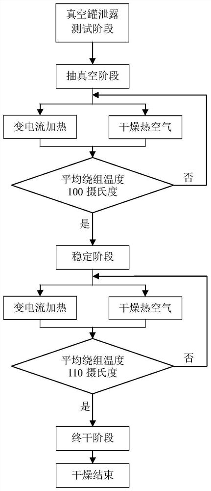
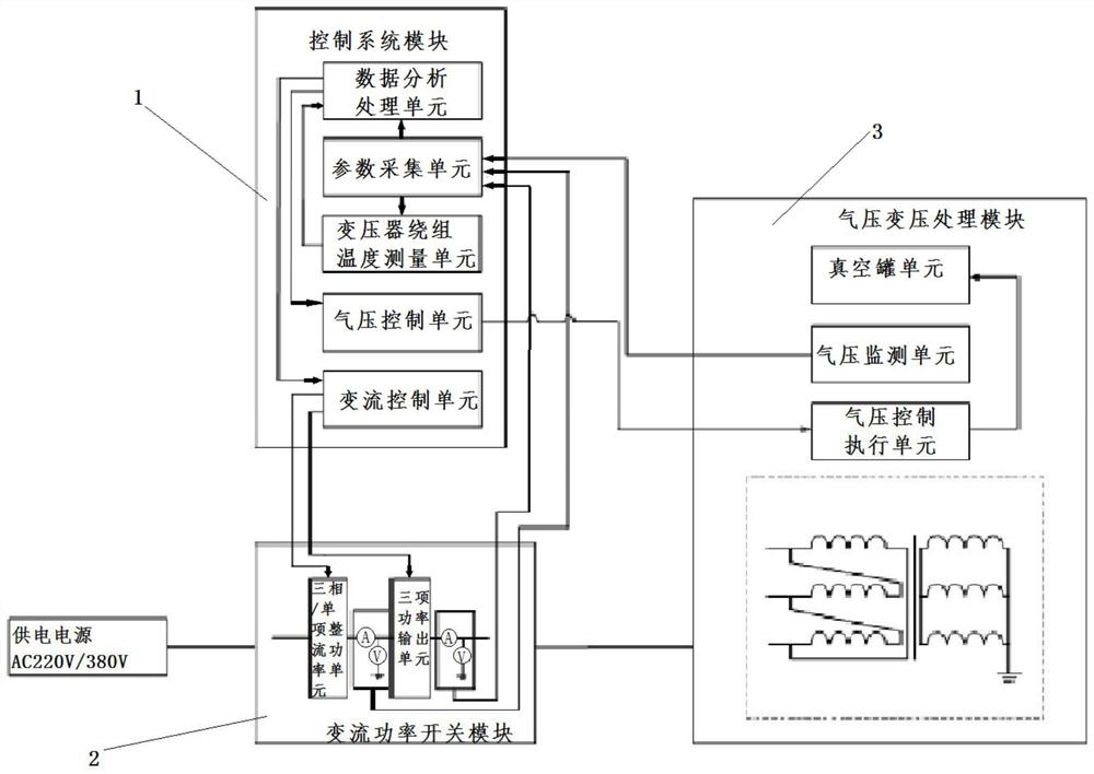
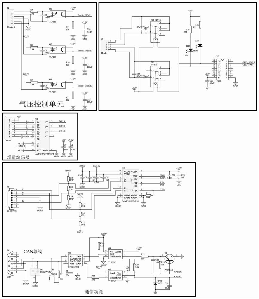
[0080] Such as Figure 1-9 As shown, a transformer drying device includes a control system module, a variable current power switch module, and an air pressure transformation processing module. The control system module collects the parameters of the built-in sensors of the variable current power switch module and the air pressure variable pressure processing module. pressure level. The 220V / 380V power supply is connected to the variable current power switch module. The built-in sensor of the module provides voltage and current electrical quantity signals to the system control module, accepts the control signals issued by the system control module, and outputs different types of current signals for power distribution. The high voltage winding of the transformer body supplies power. The built-in air pressure sensor of the air pressure variable processing module provides air pressure non-electrical signal input to the control system module, and accepts the control signal issued...


PUM


Abstract

Drying treatment of distribution transformer body Variable current power supply device and drying treatment method, this device uses the low-voltage side short-circuit method to perform variable current heating and voltage transformation, and provides a new type of three-phase transformer high and low voltage winding wire resistance measurement module, which realizes to The purpose of measuring the temperature of high and low voltage windings respectively. The data analysis unit of the device can analyze the temperature of the windings, and issue control instructions to the inverter control unit, which can realize simultaneous heating of the windings and separate heating of the windings. This device and method are well combined. Distribution transformer body structure features, better drying effect. Through the above structure and method, the present invention solves the technical problems of long processing time, poor processing effect and affecting the service life of the transformer in the prior art.

Description

technical field [0001] The invention belongs to the field of transformer equipment, and in particular relates to a distribution transformer body drying treatment converter power supply device and a drying treatment method. Background technique [0002] Distribution transformer is an important power transmission and transformation equipment, and good body insulation is an important factor to ensure its safe operation. The distribution transformer body is mainly assembled by transformer winding coils, iron cores, insulating materials and clips. Its insulating material is distributed on the iron core and coil, which is used to improve the insulation level of the transformer, improve the insulation withstand voltage and the ability to resist electric breakdown. [0003] The general structure of the distribution transformer body and the distribution of insulating materials used are as follows: the iron core is in the innermost layer, the low-voltage winding is evenly surrounded ...

Claims


Application Information

Patent Timeline
Patent Type & Authority Patents(China)
IPC IPC(8): H01F41/00H01F27/40F26B3/353
Inventor 曲通章海庭马云飞赵宏斌高健马晓婷董超刘洋吕博
Owner 沈阳中科瑞达科技有限公司
Learn More