Hand-guided well lid milling machine

A milling machine and walk-behind technology, which is applied in the field of walk-behind manhole cover milling machines, can solve the problems of high cost, high noise, limited applicable occasions, etc., and achieve the effects of simple structure, small size and light weight.

Pending Publication Date: 2019-11-19
SHANDONG IND TECH RES INST OF ZHEJIANG UNIV +1
View PDF0 Cites 0 Cited by
  • Summary
  • Abstract
  • Description
  • Claims
  • Application Information

AI Technical Summary

Problems solved by technology

[0003] At present, the separation between the manhole cover seat and the surrounding cement pavement mainly uses a skid loader to drive a manhole cover milling attachment, such as the patent "Milling Device for Manhole Cover Milling Machine". The main disadvantages are: 1) Limitation of applicable occasions: The machine itself is large in size and cannot be used for manhole cover milling in some narrow spaces. It also needs to cooperate with special lifting fixtures. Firstly, the fixture is used for positioning, and then the positioning axis of the milling machine is aligned with the positioning hole of the fixture before milling; 2 ) Loud noise: the noise of the skid steer loader itself, the noise of manhole cover milling attachments milling the road surface; 3) high cost: the cost of the skid steer loader and attachments is high

Method used


Image

  • Hand-guided well lid milling machine
  • Hand-guided well lid milling machine
  • Hand-guided well lid milling machine

Examples


Embodiment Construction

[0032] The structures involved in the present invention or the technical terms used are further described below. These descriptions are only used as examples to illustrate how the present invention is implemented, and do not constitute any limitation to the present invention.

[0033] The present invention will be further described below in conjunction with the accompanying drawings and specific embodiments. In the description of the present invention, it should be understood that the orientation or positional relationship indicated by the terms "upper", "lower", "front", "rear", "left" and "right" are based on those shown in the accompanying drawings. Orientation or positional relationship is only for the convenience of describing the present invention and simplifying the description, but does not indicate or imply that the referred position or element must have a specific orientation, be constructed and operated in a specific orientation, and thus should not be construed as ...


PUM


Abstract

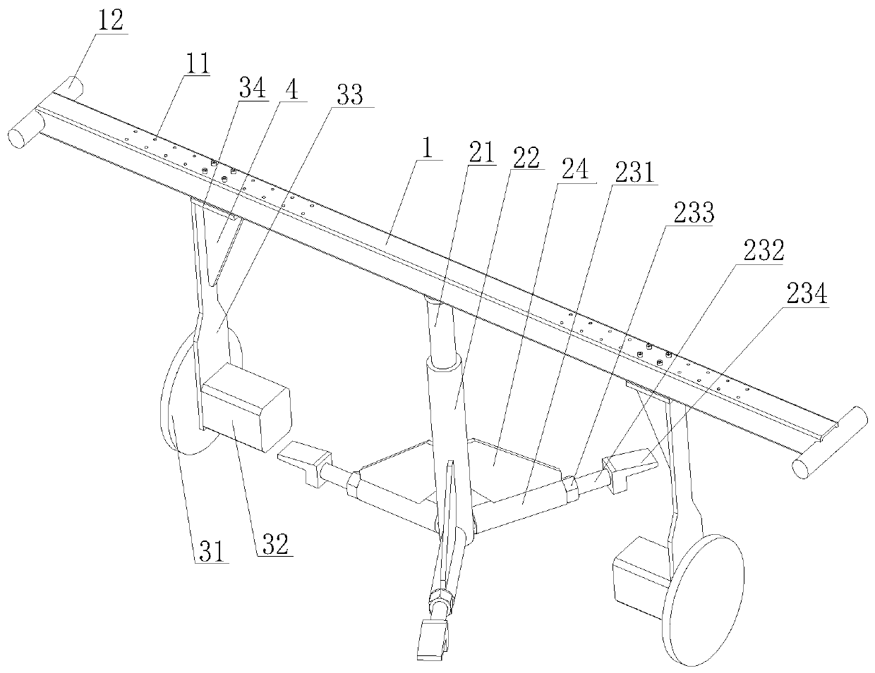
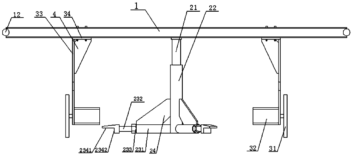
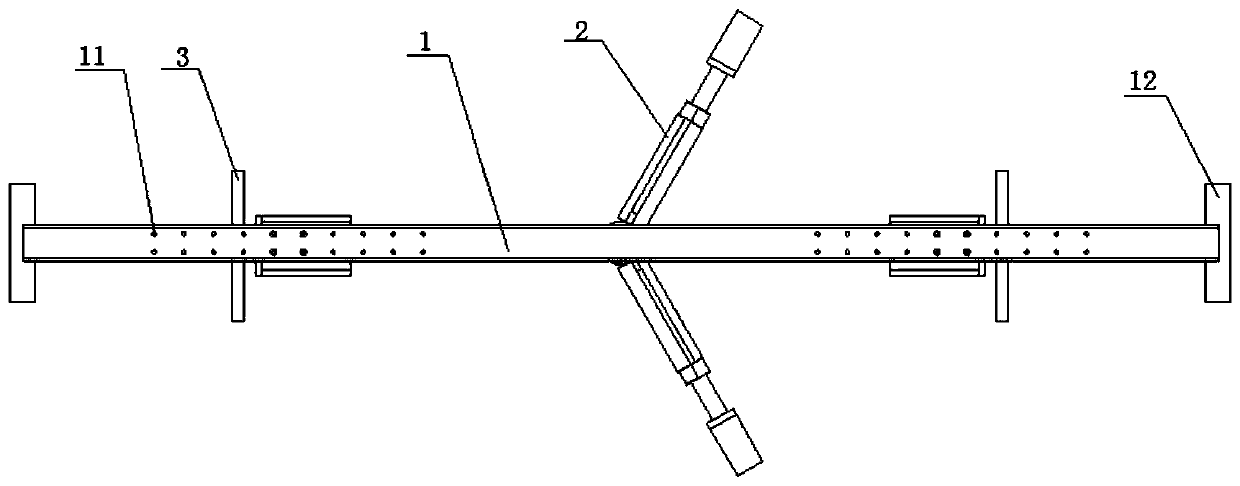
The invention discloses a hand-guided well lid milling machine. The hand-guided well lid milling machine comprises a hand-guided rack, a location mechanism and a milling mechanism, wherein the location mechanism comprises a lifting screw rod arranged on the hand-guided rack, a location support, and tensioning assemblies used for tightly jacking a well wall; the lifting screw rod and the location support are in threaded fit and coaxial; at least three groups of the tensioning assemblies are equidistantly distributed in the circumferential direction of the location support; and the milling mechanism comprises a milling wheel disc arranged on the hand-guided rack, and a motor driving the milling wheel disc to rotate. The hand-guided well lid milling machine has a location function, and is simple in structure, small in size, light in weight, and competent in well lid milling working for a narrow space.

Description

technical field [0001] The invention relates to a milling device, in particular to a hand-held manhole cover milling machine. Background technique [0002] In the city, many inspection wells will be set due to the needs of water supply, electric power, telecommunications, gas pipelines, etc. Usually the weakest and most easily broken places of inspection wells are inspection well covers and edge roads. The technical scheme of repairing the manhole cover seat and the edge is usually to separate the manhole cover seat from the surrounding cement pavement, and then utilize the clamp to take out the manhole cover seat. [0003] At present, the separation between the manhole cover seat and the surrounding cement pavement mainly uses a skid loader to drive a manhole cover milling attachment, such as the patent "Milling Device for Manhole Cover Milling Machine". The main disadvantages are: 1) Limitation of applicable occasions: The machine itself is large in size and cannot be use...

Claims


Application Information

Patent Timeline
IPC IPC(8): E01C23/088
CPCE01C23/088
Inventor 王彪邵立宗兆浩张红武杨超黄冬梅
Owner SHANDONG IND TECH RES INST OF ZHEJIANG UNIV
Why Eureka
Try Eureka