
Synchronous clutch

A clutch, friction locking technology, applied in clutches, mechanical drive clutches, mechanical equipment, etc.

Pending Publication Date: 2019-11-19
HOERBIGER ANTRIEBSTECHN HLDG
View PDF0 Cites 0 Cited by
  • Summary
  • Abstract
  • Description
  • Claims
  • Application Information

AI Technical Summary

Problems solved by technology

The goal of a compact design of the synchronous clutch can thus only be achieved to a very limited extent

Method used


Image

  • Synchronous clutch
  • Synchronous clutch
  • Synchronous clutch

Examples


Embodiment Construction

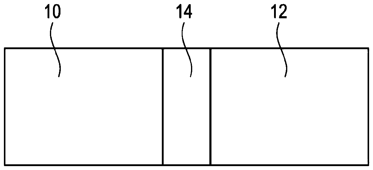
[0043] figure 1 A part of the truck is shown schematically, namely the internal combustion engine 10 , which not only drives the truck but also an auxiliary unit 12 , such as a compressor.

[0044] In the drive train between the internal combustion engine 10 and the auxiliary unit 12 there is a synchronizing clutch 14 which is designed such that it transmits high torques reliably mainly during torque fluctuations and / or load fluctuations.

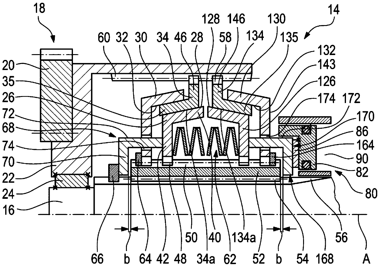
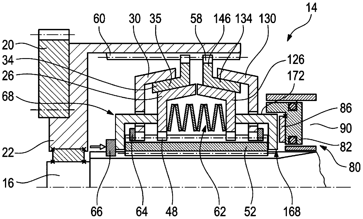
[0045] figure 2 The synchronized clutch shown in detail comprises a so-called first clutch member 16 , in particular in the form of a shaft of the auxiliary unit 12 , which forms, so to speak, the output side of the synchronized clutch 14 .

[0046] The drive side consists of: the so-called second clutch member 18, which is currently designed in multiple parts (this is not absolutely necessary); the drive gear 20 and the drive guard 22 connected to it, the The drive cover may also be referred to as the drive wheel.

[0047] The first cl...


PUM


Abstract

The invention relates to a synchronous clutch for coupling an auxiliary unit to an internal combustion engine, comprising a first clutch component (16) and a second clutch component (18), which can becoupled to each other via two friction ring sets. The friction ring sets each have a first and a second friction ring (26, 34, 126, 134) which can be coupled to each other in a torque-transmitting manner. The pre-tensioning device (52) presses the friction ring sets away from each other and into a frictional locking position, which can be opened again by means of the actuator (80).

Description

technical field [0001] The invention relates to a synchronizer clutch, in particular for coupling an internal combustion engine with an auxiliary unit, in particular a compressor. Background technique [0002] Synchronizing clutches are known in the prior art. In particular, multi-disk clutches are used to couple the internal combustion engine to the compressor. [0003] In this and in all other fields of application, the multi-disk clutch must be designed with regard to the torque that can be transmitted by it. In this case, the generally higher transmissible torques require larger multi-disc clutches than the transmissible lower torques. There is therefore a conflict of objectives between high transmissible torques and the most compact design of synchronous clutches or multi-disk clutches. [0004] For applications in which the drive is ensured by an internal combustion engine, it must also be taken into account that the torque output by such an engine can also fluctuat...

Claims


Application Information

Patent Timeline
Patent Type & Authority Applications(China)
IPC IPC(8): F16D23/04
CPCF16D23/04F16D2023/0643F16D2023/0681
Inventor 帕特里克·费舍尔彼得·K·埃克特勒克里斯多夫·特劳特王立舒迈克尔·赫希特尔尤尔根·沃尔夫尤尔根·宾德尔久罗·卡拉巴
Owner HOERBIGER ANTRIEBSTECHN HLDG
Learn More