Transmission hydraulic control system and vehicle

A technology of hydraulic control system and transmission, applied in transmission control, transmission parts, components with teeth, etc., can solve the problems of reducing transmission efficiency, increasing transmission oil churning loss, and increasing hydraulic oil volume, etc. The effect of high utilization rate of hydraulic oil, reducing oil churning loss and improving transmission efficiency

Active Publication Date: 2019-11-19
CHINA FIRST AUTOMOBILE
View PDF5 Cites 4 Cited by
  • Summary
  • Abstract
  • Description
  • Claims
  • Application Information

AI Technical Summary

Problems solved by technology

In order to ensure the oil supply pressure of the high-pressure oil circuit, the actual supply pressure of the high-pressure oil pump is much higher than the actual demand of the hydraulic system, but the pressure of the high-pressure oil circuit is greatly affected by the working conditions of the engine, and the required pressure is different under different working conditions, so the actual pressure is higher The low oil supply pressure usually causes problems such as low utilization rate of hydraulic oil and high energy consumption; in actual use, when the hydraulic oil in the high-pressure oil circuit acts on the clutch and shifting device, leakage will occur at a certain probability, and If it leaks into the first oil chamber, the hydraulic oil in the second oil chamber will gradually decrease for a long time, resulting in the failure of the high-pressure oil pump to absorb oil, while the amount of hydraulic oil in the low-pressure oil circuit will gradually increase, resulting in increased oil churning losses in the transmission , thereby reducing the transmission efficiency

Method used


Image

  • Transmission hydraulic control system and vehicle
  • Transmission hydraulic control system and vehicle
  • Transmission hydraulic control system and vehicle

Examples


Embodiment Construction

[0039] In order to make the technical problems solved by the present invention, the technical solutions adopted and the technical effects achieved clearer, the technical solutions of the embodiments of the present invention will be further described in detail below in conjunction with the accompanying drawings. Obviously, the described embodiments are only the technical solutions of the present invention. Some, but not all, embodiments. Based on the embodiments of the present invention, all other embodiments obtained by those skilled in the art without creative efforts fall within the protection scope of the present invention.

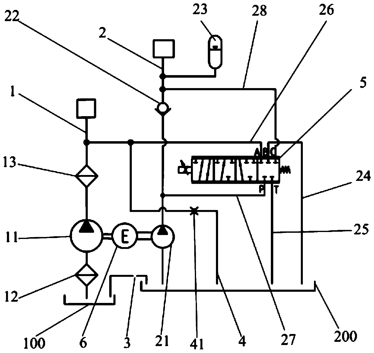
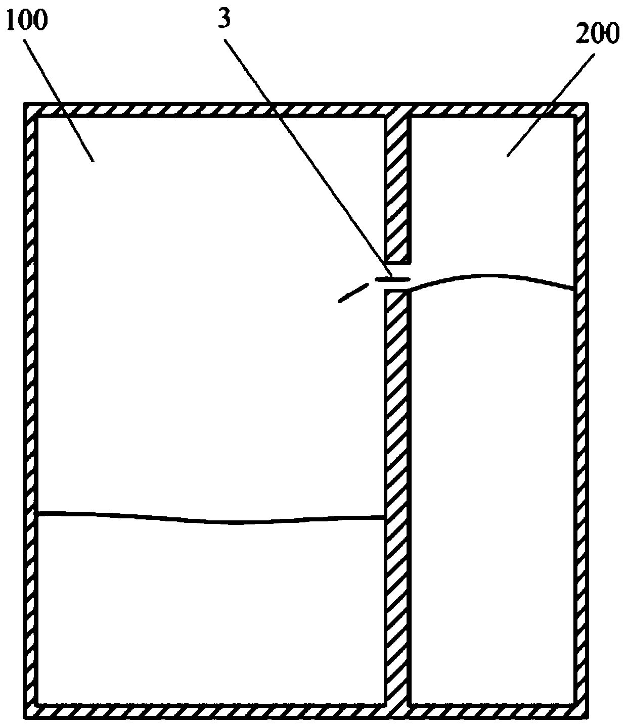
[0040] Such as Figure 1-Figure 9 As shown, this embodiment provides a transmission hydraulic control system for vehicles, which is suitable for automatic transmissions, especially for dual-clutch automatic transmissions. The transmission hydraulic control system includes a low-pressure oil circuit 1 communicating with the first oil chamber 100 , a hi...


PUM


Abstract

The invention relates to the technical field of vehicle hydraulic control systems and discloses a transmission hydraulic control system and a vehicle including the same. The transmission hydraulic control system comprises a low-pressure oil path communicating with a first oil cavity, a high-pressure oil path communicating with a second oil cavity, an oil quantity balance hole arranged between thefirst oil cavity and the second oil cavity, an oil supplementing branch arranged between the low-pressure oil path and the second oil cavity and a pressure regulating valve arranged on the high-pressure oil path. Hydraulic oil in the second oil cavity can enter the first oil cavity through the oil quantity balance hole, hydraulic oil in the low-pressure oil path can enter the second oil cavity through the oil supplementing branch, and the pressure of the high-pressure oil path can be regulated by a plurality of stations of the pressure regulating valve. According to the transmission hydrauliccontrol system and the vehicle, the pressure in the high-pressure oil path can be adjusted according to different working conditions, and the utilization rate of the hydraulic oil is high; and the quantity of the hydraulic oil in the low-pressure oil path can not only ensure sufficient lubrication to a transmission, but also avoid the excessive oil stirring loss, and therefore the transmission efficiency is high.

Description

technical field [0001] The invention relates to the technical field of vehicle hydraulic control systems, in particular to a transmission hydraulic control system and a vehicle. Background technique [0002] The main functions of the transmission hydraulic control system are control and lubrication. The control function includes controlling the closing and disconnection of the clutch and the switching between gears. The lubrication function includes providing cooling and lubricating hydraulic oil for gears, bearings and clutches. Among them, the demand of the control oil circuit for the power source is a high-pressure oil circuit with high pressure and low flow rate, and the demand for the lubricating oil circuit is a low-pressure oil circuit with low pressure and high flow rate. [0003] At present, the high-pressure oil circuit and the low-pressure oil circuit are usually set independently of each other to satisfy the control and lubrication of the transmission. In order ...

Claims


Application Information

Patent Timeline
Patent Type & Authority Applications(China)
IPC IPC(8): F16H61/02F16H57/04
CPCF16H57/0446F16H61/0021F16H61/0265F16H2061/0037
Inventor 崔江涛梁伟朋唐立中顾强
Owner CHINA FIRST AUTOMOBILE
Why Eureka
Try Eureka