Plug valve for high-pressure and high-frequency occasion

A high-pressure, high-frequency, plug valve technology, used in plugs, valve devices, engine components, etc. including cut-off devices, can solve problems such as seal failure, poor key force, inconvenient operation, etc., to reduce driving torque and friction. The effect of reduced force and easy operation

Pending Publication Date: 2019-11-19
潘世永
View PDF1 Cites 4 Cited by
  • Summary
  • Abstract
  • Description
  • Claims
  • Application Information

AI Technical Summary

Problems solved by technology

The second is the thread with axial keyway structure to achieve lifting. This structure is not suitable for high-frequency use occasions due to the poor force of the key and easy damage.
The third is that the cam mechanism realizes lifting, for example: the Chinese utility model patent whose authorization announcement number is CN2338548Y discloses a kind of cock valve, which mainly consists of a valve body, an upper bonnet and a cock body fitted in the valve body. The upper and lower ends of the cock body are equipped with balls and pressure plates, the inner wall of the valve body is provided with a grease ring groove, and a cam opening and closing mechanism is installed in the lower valve cover; although the upper and lower ends of the cock body adopt balls and pressure plate structures to reduce opening and closing. The friction torque when closing, but the pressure plate only acts as a compressive force on the balls, and the jacking and reset of the cock body are realized by the lower cam mechanism, which has a complex structure and is inconvenient to operate; moreover, the grease ring groove is used for sealing, and the jacking of the cock body The internal grease is consumed during the reset process, and the sealing effect is average, and it is easy to cause sealing failure in high-frequency use occasions

Method used


Image

  • Plug valve for high-pressure and high-frequency occasion
  • Plug valve for high-pressure and high-frequency occasion
  • Plug valve for high-pressure and high-frequency occasion

Examples


Embodiment Construction

[0025] The present invention will be further described below in conjunction with the embodiments and accompanying drawings.

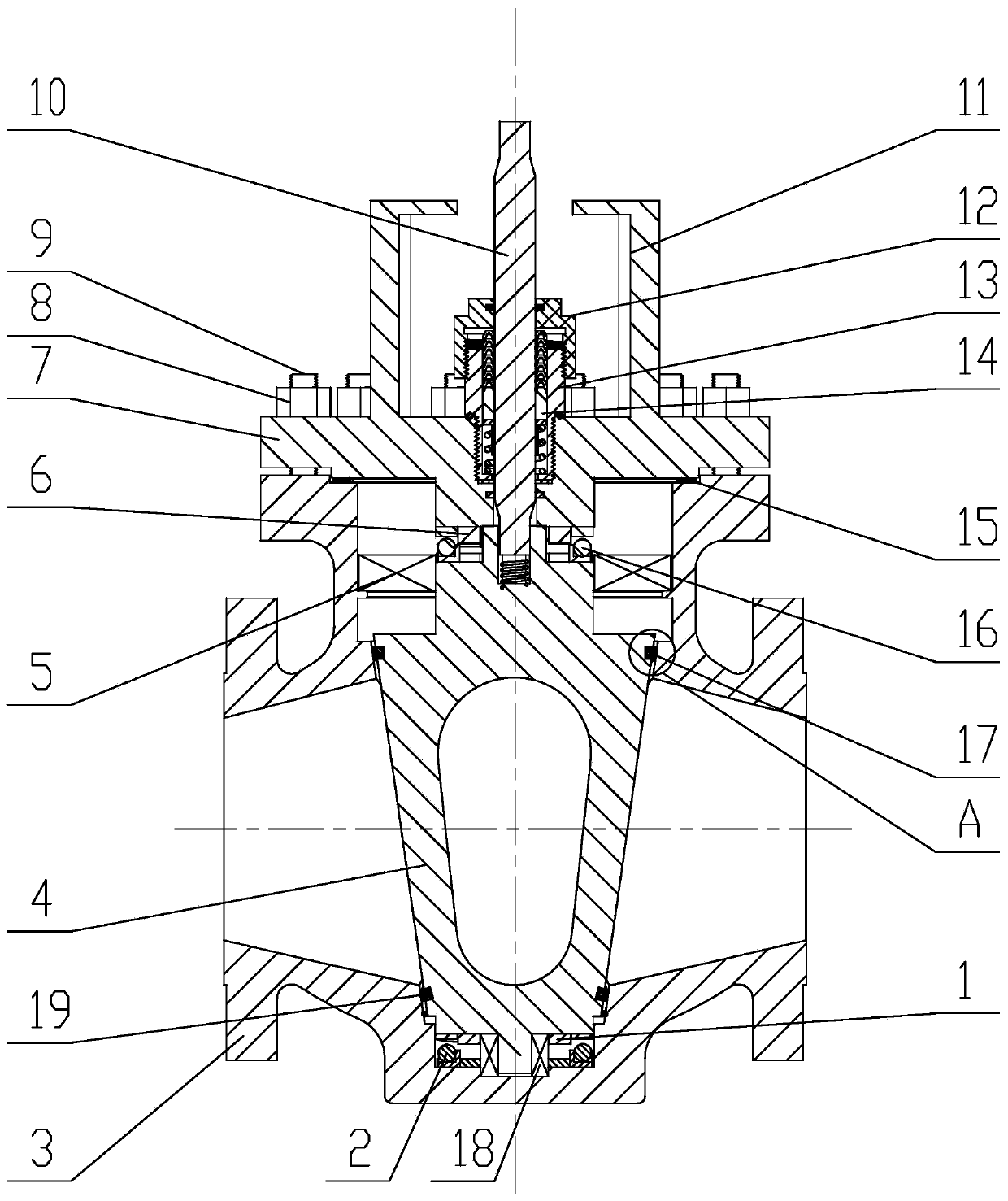
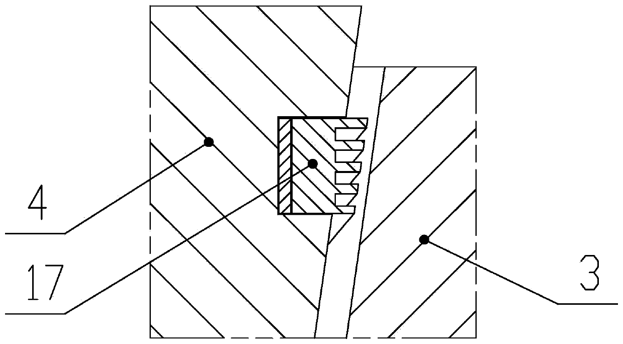
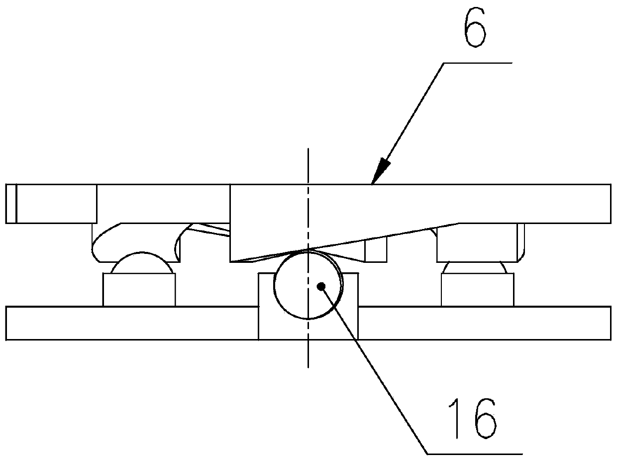
[0026] combine figure 1 , figure 2 , image 3 , Figure 4 and Figure 5 As shown, the plug valve for high-pressure and high-frequency occasions includes a valve body 3, a valve cover 7 arranged on the valve body 3, a plug body 4 rotatably arranged in the valve cavity of the valve body 3, and the lower end of which passes through the valve cover. 7. The valve stem 10 coaxially connected with the cock body 4; it also includes a pressing structure arranged between the bottom of the valve cover 7 and the top of the cock body 4, a jacking structure arranged between the bottom of the cock body 4 and the bottom of the valve cavity, And a first sealing structure and a second sealing structure arranged on the outer wall of the cock body 4 and respectively located on both sides of the flow passage hole of the cock body 4;

[0027] The pressing structure inc...


PUM


Abstract

The invention discloses a plug valve small in opening and closing friction torque and good in sealing performance for a high-pressure and high-frequency occasion. The plug valve comprises a valve body, a valve deck, a plug body and a valve rod, and further comprises a compressing structure, a jacking structure, a first sealing structure and a second sealing structure. According to the plug valve,rolling friction of upper balls and an upper slope face is used for reducing driving torque needed when the valve is turned off, and meanwhile the plug body is driven downwards and drives a sealing element downwards to be in tight fit with the sealing face of the valve body to achieve compressing sealing; the rolling friction of lower balls and a lower slope face is used for reducing driving torque needed when the valve is turned on, and meanwhile the plug body is driven to move upwards and drives the sealing element to instantly disengage from the sealing face; and abrasion between the plug body and the sealing face of the valve body is greatly reduced, and the driving torque is further reduced. Meanwhile, an upper bearing and a lower bearing are arranged on the plug body, friction forcegenerated by huge blind plate force can be greatly reduced, and the plug valve has wide market prospects.

Description

technical field [0001] The invention relates to a valve, in particular to a plug valve for high-pressure and high-frequency occasions. Background technique [0002] The plug valve is a closing member or a plunger-shaped rotary valve. By rotating 90 degrees, the flow passage hole on the plug body is connected or separated from the flow passage in the valve body to realize opening or closing. Existing cock valves are mainly divided into two types with lifting structure and non-lifting structure. [0003] Most of the plug valves without lifting structure adopt self-tight sealing between the taper surface of the plug body and the sealing surface of the valve body. Under the condition of high pressure and large diameter, the huge blind plate force can reach up to tens of tons, and the friction generated makes the valve The friction torque is huge when opening and closing; moreover, the cock body and the sealing surface of the valve body are severely worn, and the joint between t...

Claims


Application Information

Patent Timeline
Patent Type & Authority Applications(China)
IPC IPC(8): F16K5/02F16K5/16F16K5/08
CPCF16K5/0278F16K5/08F16K5/163
Inventor 潘世永
Owner 潘世永
Why Eureka
Try Eureka