A Heat Pipe System with Varying Jet Hole Height

A technology of jet tubes and jet holes, which is applied in the direction of cooling/ventilation/heating transformation, electrical components, electrical equipment structural parts, etc., can solve the problems of heat pipes being unevenly heated and unable to be effectively used, so as to avoid local overheating, Calculate the effect of increased deployment density and increased heat dissipation

Active Publication Date: 2020-05-22
SHANDONG UNIV
View PDF16 Cites 0 Cited by
  • Summary
  • Abstract
  • Description
  • Claims
  • Application Information

AI Technical Summary

Problems solved by technology

[0004] During the heat exchange process of the heat pipe, the heat pipe is unevenly heated due to different positions, resulting in ineffective utilization, so new improvements are needed

Method used


Image

  • A Heat Pipe System with Varying Jet Hole Height
  • A Heat Pipe System with Varying Jet Hole Height
  • A Heat Pipe System with Varying Jet Hole Height

Examples


Embodiment Construction

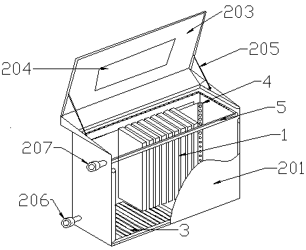
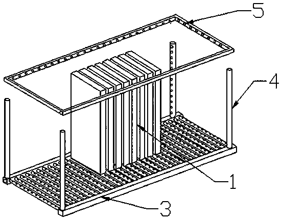
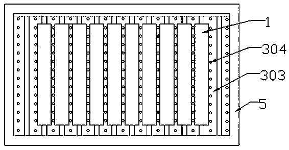
[0050] Figure 1-4 The submerged "four-corner tangential circle" self-turbulence cooling system of the present invention is shown. Such as Figure 1-4 As shown, the system includes a server 1 (or a server packaging box 6 ), a cabinet 2 , a liquid dispensing device 3 , a self-disturbance device 4 and a liquid collecting device 5 with a "square tangent circle". The cabinet 2 is provided with a cooling liquid inlet 206 and a cooling liquid outlet 207, the cooling liquid inlet 206 is located at the lower part of the side wall 201 of the cabinet, and the cooling liquid inlet 206 communicates with the liquid separator 3 , the liquid separating device 3 communicates with the "square tangential circle" spoiler 4, the liquid collecting device 5 is located below the liquid surface of the insulating cooling liquid, and the liquid collecting device 5 communicates with the cooling liquid outlet 207. The insulating cooling liquid passes through the cooling liquid inlet 206 and enters the ...


PUM


Abstract

The invention provides a heat pipe system. The heat pipe system comprises a cabinet, a liquid separating device, a self-flow disturbing device and a liquid collecting device; the cabinet is provided with a cooling liquid inlet and a cooling liquid outlet; the cooling liquid inlet is communicated with the liquid separating device; the liquid separating device is communicated with the self-flow disturbing device; the self-flow disturbing device comprises jet pipes arranged in the vertical direction of the cabinet; the openings of the lower ends of the jet pipes are communicated with a liquid separating main pipe; the upper orifices of the jet pipes are sealed; a row of jet holes is formed in each jet pipe in the vertical direction; and the distribution density of the jet holes is continuously increased in a height direction. According to the heat pipe system of the invention, the jet holes change, so that heat dissipation can be more uniform, and therefore, the service life of a server is prolonged.

Description

technical field [0001] The invention relates to the field of heat pipes, in particular to a heat pipe technology with gradually changing lengths of condensation ends. Background technique [0002] Heat pipe technology is a heat transfer element called "heat pipe" invented by George Grover of Los Alamos National Laboratory in the United States in 1963. It makes full use of the principle of heat conduction and phase change medium. The rapid heat transfer properties of the heat pipe quickly transfer the heat of the heating object to the heat source, and its thermal conductivity exceeds that of any known metal. [0003] Heat pipe technology was widely used in aerospace, military and other industries before. Since it was introduced into the radiator manufacturing industry, people have changed the traditional radiator design ideas and got rid of the single heat dissipation mode that only relies on high air volume motors to obtain better heat dissipation. The use of heat pipe tech...

Claims


Application Information

Patent Timeline
Patent Type & Authority Patents(China)
IPC IPC(8): H05K7/20
CPCH05K7/20818
Inventor 刘昱李斌李钟勇崔峥王鑫煜任霄汉邵卫王兵张宇川王宏标陈帆余道广夏爽孙海逸王文璞肖龙邓高翔
Owner SHANDONG UNIV
Why Eureka
Try Eureka