
Efficient oil removal equipment for hardware

A high-efficiency technology for hardware parts, applied in the field of high-efficiency degreasing equipment for hardware parts, can solve the problems of wearing and tearing the surface of large hardware parts, affecting the quality of finished products, pollution, etc., and achieves the effect of high degree of automation and sensitive response

Inactive Publication Date: 2019-11-22
YIWU AOLI MASCH TECH CO LTD
View PDF0 Cites 3 Cited by
  • Summary
  • Abstract
  • Description
  • Claims
  • Application Information

AI Technical Summary

Problems solved by technology

[0002] As we all know, hardware refers to tools obtained by processing and casting gold, silver, copper, iron, tin and other metals, which are often used to fix things, process things or decorate them; and in the process of metal storage, handling and processing , the surface will inevitably be polluted by some oily dirt from the outside, so oily dirt will inevitably exist in the production process of hardware parts. In order to make the surface of hardware parts clean and convenient for subsequent coating or transportation, it is necessary to degrease hardware parts; but traditional There are many types of hardware parts in different sizes. General degreasing equipment will cause friction between smaller hardware parts and large hardware parts, which will wear the surface of large hardware parts and affect the quality of finished products. In order to ensure the same batch Degreasing the hardware at the same time to reduce the error of subsequent quality inspection; therefore, it is necessary to design a high-efficiency degreasing equipment for hardware to solve the above problems

Method used


Image

  • Efficient oil removal equipment for hardware
  • Efficient oil removal equipment for hardware
  • Efficient oil removal equipment for hardware

Examples


Embodiment Construction

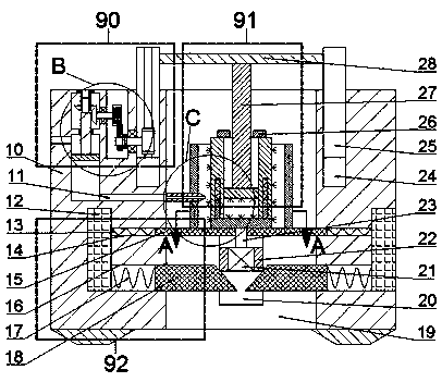
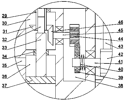
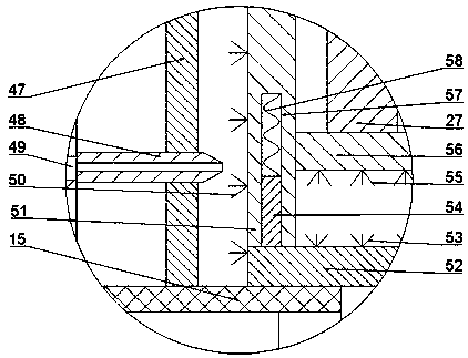
[0024] Combine below Figure 1-4 The present invention is described in detail, and for convenience of description, the orientations mentioned below are now stipulated as follows: figure 1 The up, down, left, right, front and back directions of the projection relationship itself are the same.

[0025] combined with Figure 1-4 The high-efficiency degreasing equipment for hardware includes a fuselage 10, and the fuselage 10 is provided with a working chamber 19 that opens forward and penetrates up and down;

[0026] The working chamber 19 is provided with a first cylinder 47 with its opening facing up and down. A hard pipe 48 is fixed between the first cylinder 47 and the left end wall of the working chamber 19 . The side end wall is provided with a first sliding cavity 20 with an opening forward, and a first sliding block 22 is slidably provided in the first sliding cavity 20, and a motor 21 is fixed in the first sliding block 22, and the motor 21 The top power is connected ...


PUM


Abstract

Efficient oil removal equipment for hardware comprises a machine body. The machine body is internally provided with a working cavity which is provided with a forward opening and vertically penetratesthrough the machine body. A first cylinder with an opening face facing up and down is arranged in the working cavity. A hard tube is fixedly arranged between the first cylinder and the left end wall of the working cavity. A first sliding cavity with a forward opening is formed in the rear side end wall of the working cavity. A first sliding block is slidably arranged in the first sliding cavity. Amotor is fixedly arranged in the first sliding block. The equipment removes oil from hardware with different sizes through cavity dividing, the equipment is high in overall automation degree and sensitive in response, and meanwhile, the equipment does not need to add an oil removal agent manually, so that the situation that the equipment is polluted when the oil removal agent is manually added isavoided, the equipment is clean and tidy and convenient and fast to use, the equipment removes oil from the hardware through cavity dividing, the small hardware cannot abrade the surface of the largehardware, the equipment does not damage the surface of the hardware during oil removal, and the operation is safe and reliable.

Description

technical field [0001] The invention relates to the field of industrial degreasing, in particular to a high-efficiency degreasing equipment for hardware. Background technique [0002] As we all know, hardware refers to tools obtained by processing and casting gold, silver, copper, iron, tin and other metals, which are often used to fix things, process things or decorate them; and in the process of metal storage, handling and processing , the surface will inevitably be polluted by some oily dirt from the outside, so oily dirt will inevitably exist in the production process of hardware parts. In order to make the surface of hardware parts clean and convenient for subsequent coating or transportation, it is necessary to degrease hardware parts; but traditional There are many types of hardware parts in different sizes. General degreasing equipment will cause friction between smaller hardware parts and large hardware parts, which will wear the surface of large hardware parts and ...

Claims


Application Information

Patent Timeline
IPC IPC(8): B08B1/04B08B3/08B08B3/10B08B13/00
CPCB08B3/08B08B3/10B08B13/00B08B1/32B08B1/12
Inventor 许丹
Owner YIWU AOLI MASCH TECH CO LTD
Learn More