Constrained Radial-Axial Roll Forming Method for Large Thin-walled External T-shaped Ring Members

A ring-shaped component, axial rolling technology, applied in metal rolling and other directions, to achieve the effect of high efficiency, high material utilization rate, and small forming force

Active Publication Date: 2020-08-25
WUHAN UNIV OF TECH
View PDF8 Cites 0 Cited by
  • Summary
  • Abstract
  • Description
  • Claims
  • Application Information

AI Technical Summary

Problems solved by technology

At present, there is no relevant report on constrained radial axial rolling forming technology at home and abroad

Method used


Image

  • Constrained Radial-Axial Roll Forming Method for Large Thin-walled External T-shaped Ring Members
  • Constrained Radial-Axial Roll Forming Method for Large Thin-walled External T-shaped Ring Members
  • Constrained Radial-Axial Roll Forming Method for Large Thin-walled External T-shaped Ring Members

Examples


Embodiment Construction

[0034] In order to have a clearer understanding of the technical features, purposes and effects of the present invention, the specific implementation manners of the present invention will now be described in detail with reference to the accompanying drawings.

[0035] The large thin-walled outer T-shaped annular component constrained diameter axial rolling method of the present invention comprises the following steps:

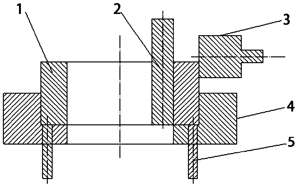
[0036] (1) Determination of the initial rolling position. Such as figure 1 As shown, the annular preform 1 is placed in the restraint mold 4, and the bottom surface of the blank is flat with the surface of the restraint mold 4. The outer surface of the radial feed roll 2 is tangent to the inner surface of the blank, and the bottom surface is flat with the blank. The end surface of the axial feed roll 3 is tangent to the annular preform 1, and its axis is 50 mm away from the upper surface of the constraining die 4.

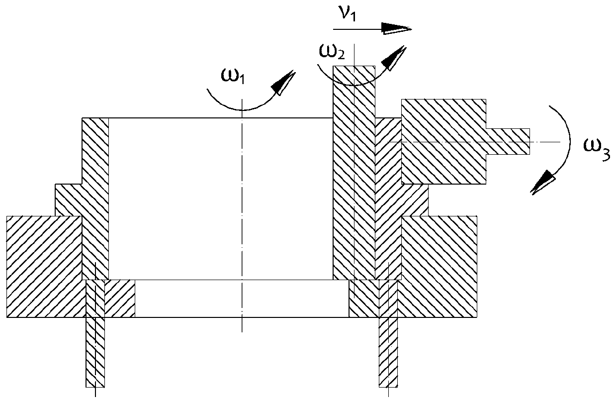
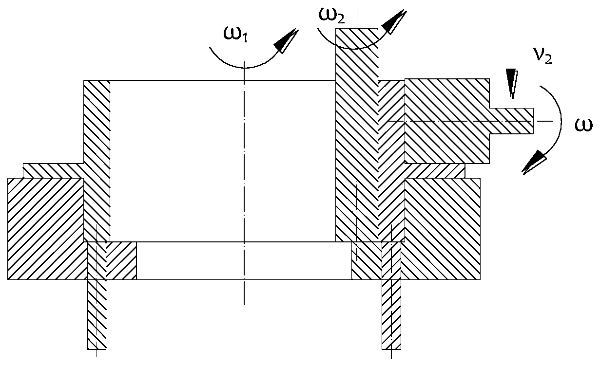
[0037] (2) Constrained radial and axial ro...


PUM


Abstract

The invention relates to a constraining radial-axial roll-forming method for a large thin-wall outer T-shaped annular component. The constraining radial-axial roll-forming method comprises the following steps that S1, an annular prefabricated blank is placed in a constraint mold, the bottom face of the annular prefabricated blank is in contact with the lower end face in the constraint mold, and aradial feeding roll is arranged in the annular prefabricated blank; S2, at a radial rolling stage, after rolling is started, the constraint mold drives the annular prefabricated blank to uniformly rotate around the axis of the constraint mold at the rotating speed omega1, the radial feeding roll rotates around the axis of itself at the rotating speed omega2 and meanwhile does feeding motion at thespeed v1 in the radial direction, and an axial feeding roll uniformly rotates around the axis of itself at the rotating speed omega3 and does not do translational motion; S3, at an axial rolling stage, the constraint mold continues to uniformly rotate around the axis of itself at the rotating speed omega1, the position of the radial feeding roll is kept fixed, and the axial feeding roll starts tocarry out downward feeding at the speed v2 in the axial direction while uniformly rotating around the axis of itself; and S4, operation at a demolding stage is carried out. According to the constraining radial-axial roll-forming method, high-performance, high-efficiency, low-cost and near-net forming manufacturing of the large thin-wall complex annular component is achieved.

Description

technical field [0001] The invention relates to the field of forming and manufacturing large-scale ring parts, and more specifically relates to a constrained radial-axial rolling forming method of a large-scale thin-walled outer T-shaped ring member. Background technique [0002] Large thin-walled outer T-shaped ring components are key components in the fields of aviation, aerospace, ships, wind power, weaponry and other fields. How to manufacture large thin-walled outer T-shaped rings with high performance, high efficiency and low cost has become an important international equipment manufacturing Hotspots of technology research. The large thin-walled outer T-shaped annular member has thin wall thickness, large axial height, large diameter, and extreme geometric dimensions. At present, such complex thin-walled components are mainly manufactured by machining and welding. The machining method is to first simplify the large and complex thin-walled outer T-shaped ring member i...

Claims


Application Information

Patent Timeline
Patent Type & Authority Patents(China)
IPC IPC(8): B21H1/06
CPCB21H1/06
Inventor 韩星会华林杨思伟胡亚雄田端阳
Owner WUHAN UNIV OF TECH
Why Eureka
Try Eureka