
Novel hole-drilling image collecting robot and application method thereof

An image acquisition and robotic technology, applied in manipulators, manufacturing tools, etc., can solve the problems of the lens without any anti-fog treatment and anti-collision protection, the pause of image acquisition and the long acquisition time, and the inability to clean up in the borehole. Guaranteed continuity and integrity, full-featured, time-saving effects

Pending Publication Date: 2019-11-22
SHANDONG UNIV OF SCI & TECH
View PDF9 Cites 3 Cited by
  • Summary
  • Abstract
  • Description
  • Claims
  • Application Information

AI Technical Summary

Problems solved by technology

The borehole peeping instrument includes a camera probe, a push rod, an imaging host and a metal frame. The camera probe is arranged at the end of the push rod, and the metal frame is provided with a depth counter pulley. The hole peeper can be operated by a single person, but it is necessary to use a push rod to push the camera to the borehole. Multiple push rods are connected through screw joints and screw interfaces, resulting in a pause in image acquisition and longer acquisition time, and the lens does not have any anti-fog treatment and Anti-collision protection, limited application conditions
[0007] The invention with the application number 2016105853264 discloses a self-adaptive centering and antifouling device for the camera of a mining borehole peeping instrument, including a probe rod, a camera, a cable, a buckle, a fixed plate, a positioning nut, and an elastic steel wire. Its main purpose is to make the The camera is located in the center of the borehole to prevent the camera from touching the hole wall. However, when the lens advances to the mudstone and broken area, the elastic steel wire is embedded in the broken area, which prevents the lens from advancing, and the surface of the lens is condensed by water vapor, which cannot be cleaned in the borehole. Can withdraw orifice for cleaning, time wasted

Method used


Image

  • Novel hole-drilling image collecting robot and application method thereof
  • Novel hole-drilling image collecting robot and application method thereof
  • Novel hole-drilling image collecting robot and application method thereof

Examples


Embodiment Construction

[0040] The technical solution of this patent will be further described in detail below in conjunction with specific embodiments.

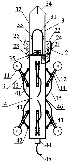
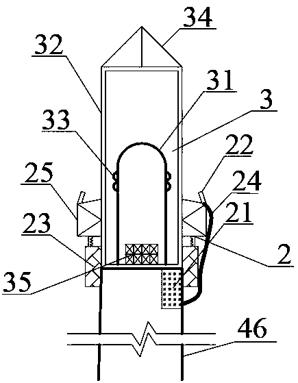
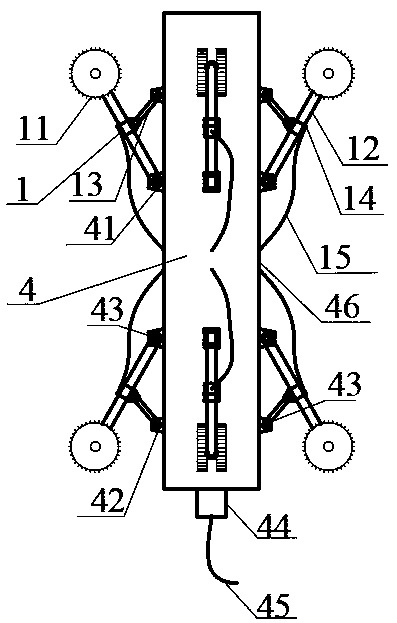
[0041] A novel drilling image acquisition robot includes a self-advancing device 1, a cleaning device 2, an acquisition device 3, a connecting device 4 and a control device 5; the self-advancing device 1 is installed on the outside of the connecting device to provide the present invention with a Power; the cleaning device 2 is installed in the middle of the collection device 3 and the connection device 4, and can clean the protective shell 32 of the present invention to ensure the clarity of image collection; the collection device 3 is installed on the top of the connection device 4 and is The rock formation image acquisition part of the present invention; the connection device 4 connects the various parts of the present invention; the control device 5 can send instructions to control the present invention to implement the image acquisition function...


PUM


Abstract

The invention discloses a novel hole-drilling image collecting robot and an application method thereof and solves the problems in an existing hole-drilling image collecting process. The novel hole-drilling image collecting robot comprises a self-drilling device, a cleaning device, a collecting device, a connecting device and a control device. The self-drilling device is provided with eight self-rotating anti-skid rubber wheels capable of adjusting supporting angles, and is internally provided with a high torque motor capable of driving the novel hole-drilling image collecting robot to advancein the middle of a drilled hole. The cleaning device can clean a protecting shell of a protecting lens in the drilled hole, so that the image collecting precision is improved. The control device is provided with a control key and a function key capable of operating the advancing speed, the gesture and the brightness of a light source during image collection, and storing the collected information in real time. The novel hole-drilling image collecting robot is suitable for detecting the drilled hole in a top plate of a coal mine tunnel and has the characteristics of being simple and convenient to operate, high in collecting efficiency and high in collecting precision. The collected data can reflect surrounding rock deformation and crushing characteristics of a tunnel roof truly.

Description

technical field [0001] The invention relates to the field of coal mine rock formation detection, in particular to a novel drilling image acquisition robot. Background technique [0002] As an important energy fuel and chemical raw material, coal plays an important role in the development of the national economy and people's lives. In order to maximize the exploitation of coal resources and save production costs, most coal seams are mined by roof cutting, pressure relief and roadway retention along the gob. [0003] Coal seam mining will inevitably cause the overlying strata to fracture, break, caving and deformation of the underlying strata. The height of the caving zone of the working face and the deformation characteristics of the roof are important parameters for the support of gob-side entry retaining. Therefore, the detection of the surrounding rock of the roadway roof has strong guiding significance for the safe production of the working face. In addition, at present...

Claims


Application Information

Patent Timeline
IPC IPC(8): B25J5/00B25J11/00B25J19/00B25J19/02
CPCB25J11/00B25J5/007B25J19/00B25J19/02B25J19/023B25J19/0058
Inventor 朱庆文冉金林李廷春赵爽殷齐浩王洪闪王凯杜贻腾
Owner SHANDONG UNIV OF SCI & TECH
Learn More