
Hybrid power unmanned aerial vehicle with two kinds of rotors and control method thereof

A hybrid power and drone technology, applied in the field of drones, can solve problems such as limiting drone applications, drone defects, crashes, etc., to ensure control flexibility and stability, and to facilitate miniaturization design , The effect of reducing the consumption of electric energy

Pending Publication Date: 2019-11-22
BEIFANG UNIV OF NATITIES
View PDF1 Cites 2 Cited by
  • Summary
  • Abstract
  • Description
  • Claims
  • Application Information

AI Technical Summary

Problems solved by technology

However, the power storage capacity of the battery is limited after all, which leads to the short battery life of the UAV, and the small size of the rotor also makes the load of the UAV small, which limits the wider application of the UAV.
[0003] The Chinese invention patent application with the publication number CN107140192A discloses a hybrid unmanned aerial vehicle, which is equipped with a lift rotor and a control rotor respectively. The lift rotor is driven by a fuel motor, and the control rotor is driven by a motor, which can maintain the stable control of the drone. , and can improve the load capacity and endurance of the UAV, but the UAV still has defects
For example, since the lift rotors are arranged symmetrically on the edge of the frame, to achieve stable control of the UAV, it is necessary to keep the two lift rotors synchronous and rotate in opposite directions at the same speed. To achieve the requirement of the same speed, it is even more difficult to control the synchronous rotation. Therefore, the UAV is actually a stable control under ideal conditions, which is difficult to achieve in practical applications. When the two lift rotors cannot rotate synchronously and at the same speed , will cause the entire UAV to be unable to maintain balance and stability, and may cause a crash

Method used


Image

  • Hybrid power unmanned aerial vehicle with two kinds of rotors and control method thereof
  • Hybrid power unmanned aerial vehicle with two kinds of rotors and control method thereof

Examples


Embodiment Construction

[0026] The following will clearly and completely describe the technical solutions in the embodiments of the present invention with reference to the accompanying drawings in the embodiments of the present invention. Obviously, the described embodiments are only some, not all, embodiments of the present invention. The components of the embodiments of the invention generally described and illustrated in the figures herein may be arranged and designed in a variety of different configurations. Accordingly, the following detailed description of the embodiments of the invention provided in the accompanying drawings is not intended to limit the scope of the claimed invention, but merely represents selected embodiments of the invention. Based on the embodiments of the present invention, all other embodiments obtained by those skilled in the art without making creative efforts belong to the protection scope of the present invention.

[0027] The hybrid unmanned aerial vehicle with two k...


PUM


Abstract

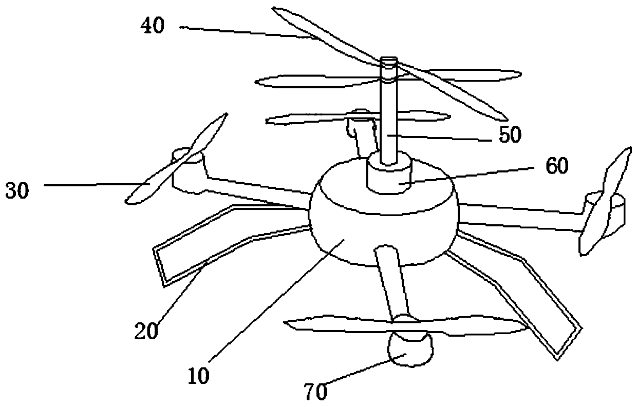
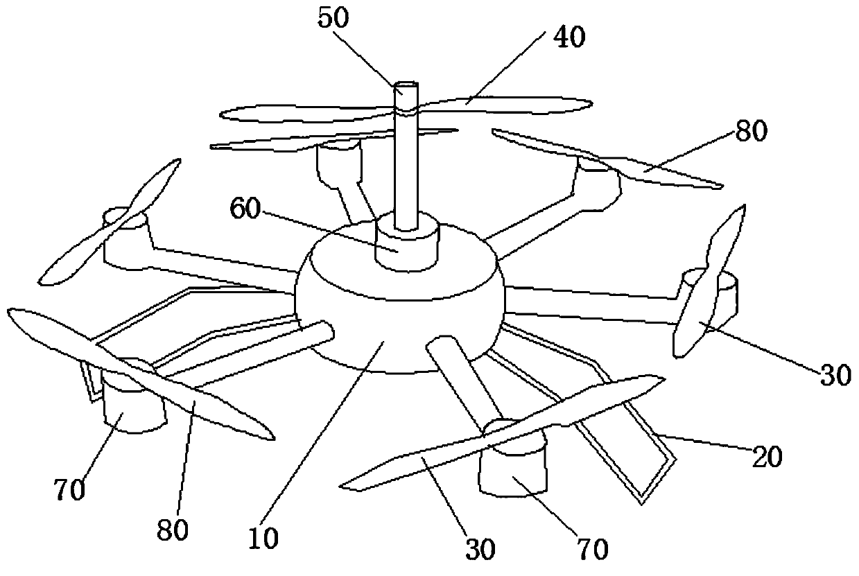
The invention relates to a hybrid power unmanned aerial vehicle with two kinds of rotors and a control method thereof. The unmanned aerial vehicle comprises a vehicle body, the edge of the vehicle body is provided with at least one pair of control rotors, the two control rotors in each pair are symmetrically arranged, the control rotors are driven by a motor, the center of the vehicle body is provided with a plurality of lifting rotors, and the lifting rotors are arranged on the same rotating shaft and driven by the same fuel motor. The invention provides the hybrid power unmanned aerial vehicle with two kinds of rotors. According to the unmanned aerial vehicle, the multiple lifting rotors are arranged in the center of the vehicle body and arranged on the same rotating shaft, all the lifting rotors can synchronously rotate at the same speed when the rotating shaft is driven by the fuel motor to rotate, and therefore the flight stability of the unmanned aerial vehicle can be reliably guaranteed.

Description

technical field [0001] The invention relates to the technical field of unmanned aerial vehicles, in particular to a hybrid unmanned aerial vehicle with two rotors and a control method thereof. Background technique [0002] UAVs, also called unmanned aerial vehicles, have been widely used in various fields. Considering factors such as stability and ease of control, current drones only have multiple rotors of smaller sizes in pairs, and are powered by batteries, and the DC motors drive the wings to rotate. However, the power storage capacity of the battery is limited after all, which leads to the short battery life of the drone, and the small size of the rotor also makes the load of the drone not large, which limits the wider application of the drone. [0003] The Chinese invention patent application with the publication number CN107140192A discloses a hybrid unmanned aerial vehicle, which is equipped with a lift rotor and a control rotor respectively. The lift rotor is drive...

Claims


Application Information

Patent Timeline
Patent Type & Authority Applications(China)
IPC IPC(8): B64C39/02B64C27/08B64C27/14B64C27/12B64D27/02
CPCB64C39/02B64C27/08B64C27/14B64C27/12B64D27/02B64U50/11B64U50/19B64U10/10B64D27/026
Inventor 张白肖岩王志会
Owner BEIFANG UNIV OF NATITIES
Learn More