Unified buffering device for closed loading and unloading operation

A buffer device and operation technology, which is applied in the direction of distribution device, special distribution device, liquid distribution, transportation or transfer device, etc., can solve the problems of dirty oil unloading pipe, laborious lifting, heavy oil unloading pipe, etc., and speed up the speed of oil unloading , the effect of reducing air resistance

Pending Publication Date: 2019-11-22
TIANJIN ZHENGFANG TECH DEV
View PDF0 Cites 0 Cited by
  • Summary
  • Abstract
  • Description
  • Claims
  • Application Information

AI Technical Summary

Problems solved by technology

[0004] 1. When the oil is unloaded in a closed manner, the oil in the tank truck is discharged to the transfer tank by gravity. Since the transfer tank is sealed, the gas is not discharged during the oil unloading process, so an air resistance is formed. The transfer tank is vertical It is placed directly on the bracket, so when pumping to the end, because the height of the bottom of the tank truck is higher than the height of the oil inlet on the transfer tank, combined with the gas in the transfer tank, the pressure in the transfer tank is higher than that in the oil tank Therefore, there will be a problem that the oil pumped into the final tanker cannot be pumped out;
[0005] 2. The oil discharge pipe is very heavy. At present, the oil discharge pipe will hang on the ground and make the oil discharge pipe dirty when the oil is not discharged. It takes two people to lift the oil discharge pipe when it is unloaded again. It is more laborious to lift it.

Method used


Image

  • Unified buffering device for closed loading and unloading operation
  • Unified buffering device for closed loading and unloading operation
  • Unified buffering device for closed loading and unloading operation

Examples


Embodiment Construction

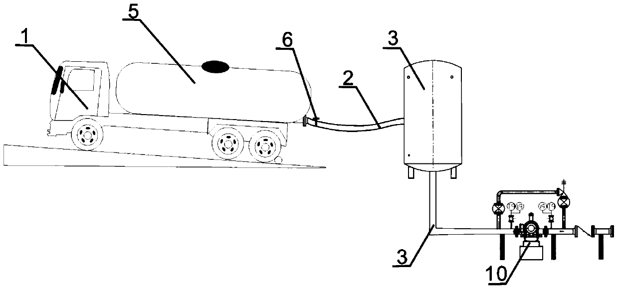
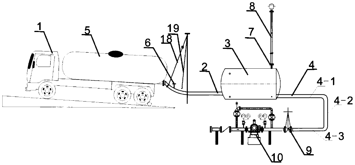
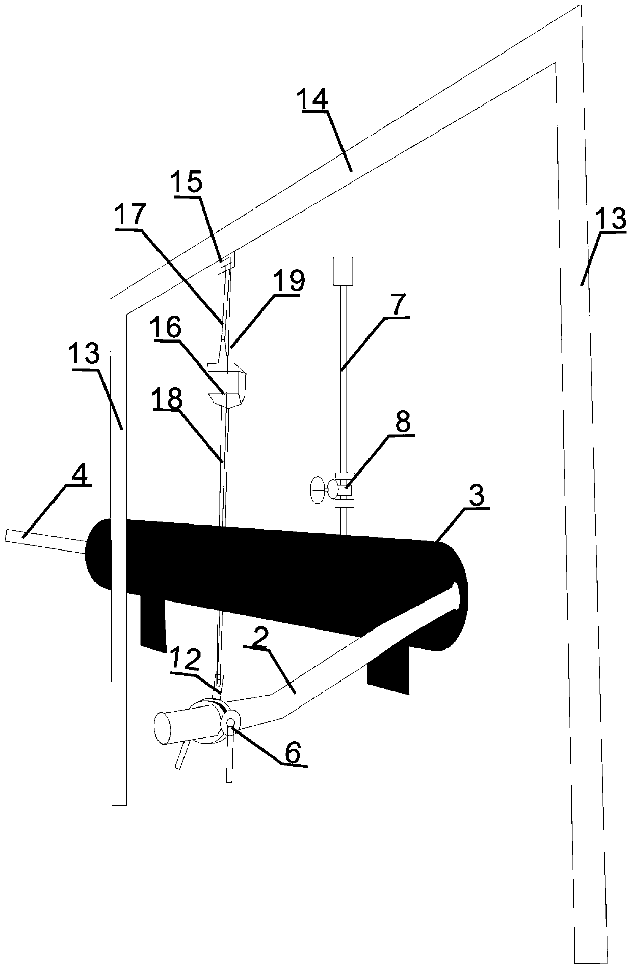
[0035] This embodiment is used for the integrated buffer device for airtight loading and unloading operations, including an adapter tank 3, one end of the adapter tank is connected to the oil discharge pipe 2, and the other end is the oil outlet pipe 4, and the circumference of the adapter tank 3 is provided with a row The air pipe 7, the electric valve I8 is arranged on the exhaust pipe 7;

[0036] The oil outlet pipe 4 is U-shaped, and the oil outlet pipe 4 is divided into pipe I4-1, pipe II4-2, and pipe III4-3. One end of the pipe I4-1 is connected to the oil storage tank 5, and the other end is connected to the The tube II4-2, one end of the tube III4-3 is connected to the tube II4-2, and the other end is connected to the oil storage tank 5, the tube I4-1 and the tube III4-3 are set up and down, and the tube II4-3 2 The pipe III 4-3 in the direction of the pipe III 4-3 is provided with an electric valve II 9 and a pump 10 in sequence;

[0037] The oil outlet pipe 4 is arr...


PUM


Abstract

The invention provides a unified buffering device for closed loading and unloading operation which comprises a transferring tank; one end of the transferring tank is connected with an oil dischargingpipe; the other end of the transferring tank is connected with an oil outlet pipe; an exhaust pipe is arranged all over the body of the transferring tank and is provided with an electric valve I; theoil outlet pipe is in a U shape and is divided into a pipe I, a pipe II and a pipe III; one end of the pipe I is connected with an oil storage tank, and the other end is connected with the pipe II; one end of the pipe III is connected with the pipe II, and the other end I is connected with the oil storage tank; the pipe I and the pipe III are arranged up and down; the position, in a direction fromthe pipe II to the pipe III, of the pipe III is sequentially provided with an electric valve II and a pump; the oil discharging pipe is provided with a connecting sheet I with a hole; the top ends oftwo supporting columns are connected through a cross beam; the cross beam is provided with a connecting sheet II with a hole; the two ends of a connecting rope are connected with a telescopic buckleand the connecting sheet II respectively; the telescopic buckle is connected with a pulling rope; and a hook is arranged on the pulling rope and is hung in the hole in the connecting sheet I. The unified buffering device has the beneficial effects that oil in the oil tank can be clearly unloaded, and the oil discharging pipe cannot be hung down on the ground.

Description

technical field [0001] The invention relates to the technical field of automobile oil unloading, in particular to an integrated buffer device used for airtight loading and unloading operations. Background technique [0002] The crude oil collected in the oil extraction operation area, according to the difference in the output of the operation area, is simply processed on the spot, and then collected to the centralized loading and unloading point through pipeline or land transportation, such as loading station, refueling and water injection station, combined station, etc. After a certain amount of storage is reached, it will be transported to refining and chemical enterprises through relatively centralized channels for further processing. Since the distances between domestic oil production points are relatively long, and the oil output of each point is not large, the use of pipeline transportation to realize crude oil transportation is relatively rare. The crude oil produced ...

Claims


Application Information

Patent Timeline
Patent Type & Authority Applications(China)
IPC IPC(8): B67D7/04B67D7/78
CPCB67D7/04B67D7/78
Inventor 李艺李聪韩霞孙文金鑫兰文沙
Owner TIANJIN ZHENGFANG TECH DEV
Why Eureka
Try Eureka