Mounting method for prefabricated parts based on strong light laser positioning technology

A technology of prefabricated components and laser positioning, applied in the direction of optical devices, measuring devices, building structures, etc., can solve the problems of increasing the probability of high-altitude fall accidents and reducing the installation speed of prefabricated components, so as to reduce the probability of high-altitude fall hazards, Accelerated construction speed and accurate positioning

Inactive Publication Date: 2019-11-22
CHINA MCC17 GRP
View PDF7 Cites 4 Cited by
  • Summary
  • Abstract
  • Description
  • Claims
  • Application Information

AI Technical Summary

Problems solved by technology

[0005] Aiming at the deficiencies of the existing technology, the present invention provides a prefabricated component installation method based on strong light laser positioning technology, which solves the problem of manual alignment of the existing prefabricated shear wall panel installation technology in the construction process of prefabricated buildings. The installed prefabricated components are positioned. Specifically, the workers of the on-site prefabricated component installation team bend down to align the reserved holes on the prefabricated components with the pre-embedded steel bars, and the prefabricated components are hoisted and placed through repeated attempts. Such a construction The method greatly reduces the installation speed of prefabricated components. At the same time, the installation of prefabricated shear wall exterior wall panels is a problem that increases the probability of high-altitude fall accidents because workers stand near the edge of the building.

Method used


Image

  • Mounting method for prefabricated parts based on strong light laser positioning technology
  • Mounting method for prefabricated parts based on strong light laser positioning technology

Examples


Embodiment Construction

[0019] The technical solutions in the embodiments of the present invention will be clearly and completely described below with reference to the accompanying drawings in the embodiments of the present invention. Obviously, the described embodiments are only a part of the embodiments of the present invention, but not all of the embodiments. Based on the embodiments of the present invention, all other embodiments obtained by those of ordinary skill in the art without creative efforts shall fall within the protection scope of the present invention.

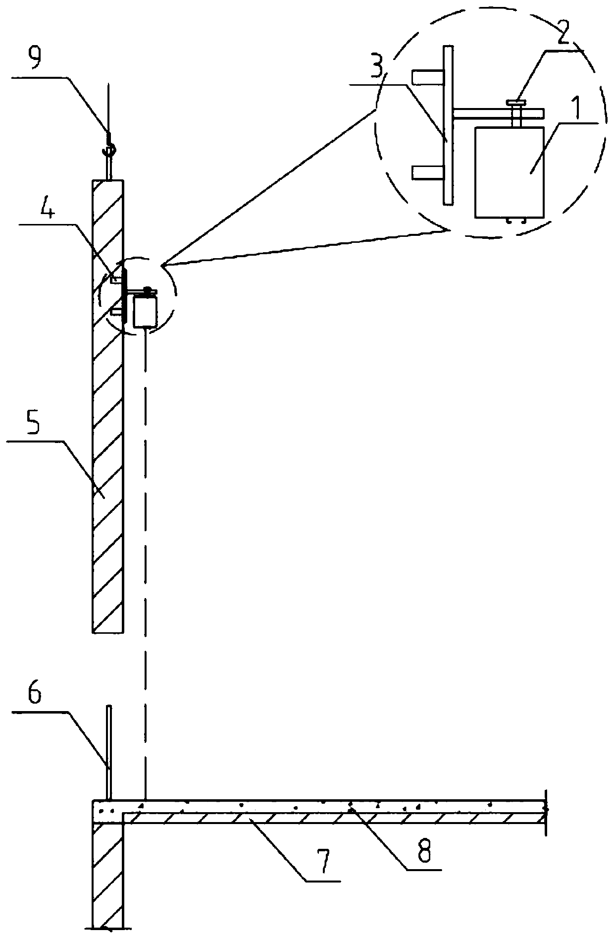
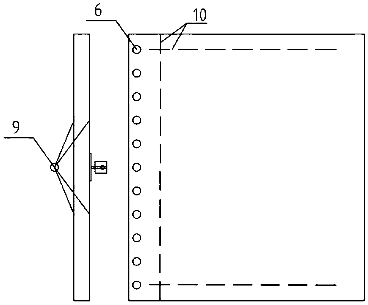
[0020] see Figure 1-2 , the present invention provides a technical solution: a prefabricated component installation method based on strong light laser positioning technology, including tower crane, strong light laser instrument 1, bolt sleeve 4, prefabricated component 5, embedded steel bar 6 and cast-in-place concrete floor slab 8. The specific operations are as follows:

[0021] S1. Make a base 3, and fix the strong light laser 1 ...


PUM


Abstract

The invention discloses a mounting method for prefabricated parts based on a strong light laser positioning technology and relates to the technical field of prefabricated construction. The mounting method for the prefabricated parts based on the strong light laser positioning technology comprises a tower crane, a strong laser instrument, bolt sleeves, a prefabricated part, embedded bars and a cast-in-situ concrete slab. The mounting method comprises the following specific operations: S1, producing a base, and fixing the strong laser instrument on the base; S2, selecting the bolt sleeves and fixing the base in the bolt sleeves through bolts; and S3, embedding the bolt sleeves in the prefabricated part. According to the mounting method for the prefabricated parts based on the strong light laser positioning technology, the strong laser instrument is arranged and fixed on the prefabricated part, and the prefabricated part is positioned needing to be mounted is positioned by adopting laseremitted by the strong light laser instrument instead of manual positioning, so that the probability of high falling potential hazard of constructors is reduced; and meanwhile, the construction speed is promoted to be greatly increased and the positioning is more accurate.

Description

technical field [0001] The invention relates to the technical field of prefabricated building construction, in particular to a prefabricated component installation method based on a strong light laser positioning technology. Background technique [0002] With the development of the economy and the innovation of the construction industry, my country's housing construction has also achieved rapid development and progress, and has become the development direction of the entire field. Under the background of economic speed regulation, various factors such as resource constraints, increasing environmental pressure, changes in population structure, and rising labor costs in traditional on-site construction methods. All make the development of the construction industry encounter bottlenecks. Looking at the current situation at home and abroad, the transformation and upgrading of the traditional construction industry and the promotion of construction industrialization are the only ...

Claims


Application Information

Patent Timeline
Patent Type & Authority Applications(China)
IPC IPC(8): E04G21/14E04G21/16G01B11/00
CPCE04G21/14E04G21/167G01B11/00
Inventor 薛晨张晓波柳荣芳
Owner CHINA MCC17 GRP
Why Eureka
Try Eureka