Medical airtight door

An airtight door and door frame technology, applied in the field of medical airtight doors, can solve the problems of easy fogging, poor air tightness, and inability to detect sealing, etc., and achieve the effect of strong air tightness and preventing fogging

Pending Publication Date: 2019-11-22
广州海洁尔医疗设备有限公司
View PDF0 Cites 5 Cited by
  • Summary
  • Abstract
  • Description
  • Claims
  • Application Information

AI Technical Summary

Problems solved by technology

[0002] Medical airtight doors are mainly to protect the cleanliness and safety of the indoor environment. Different from ordinary doors, because they need to isolate the external air and bacteria, so as to ensure that the air in the operating room is clean and sterile, they must have good sealing, and A glass window is required to facilitate the observation of the interior and ensure that the glass window will not fog up. In the existing medical purification project, the airtight door used has the problem of poor airtightness, and cannot detect whether it is sealed, and the temperature difference between indoor and outdoor is large. It is also easy to fog, so there is a need for a medical airtight door that can detect the sealing effect and has good sealing performance, and the glass window will not fog

Method used


Image

  • Medical airtight door
  • Medical airtight door
  • Medical airtight door

Examples


Embodiment 1

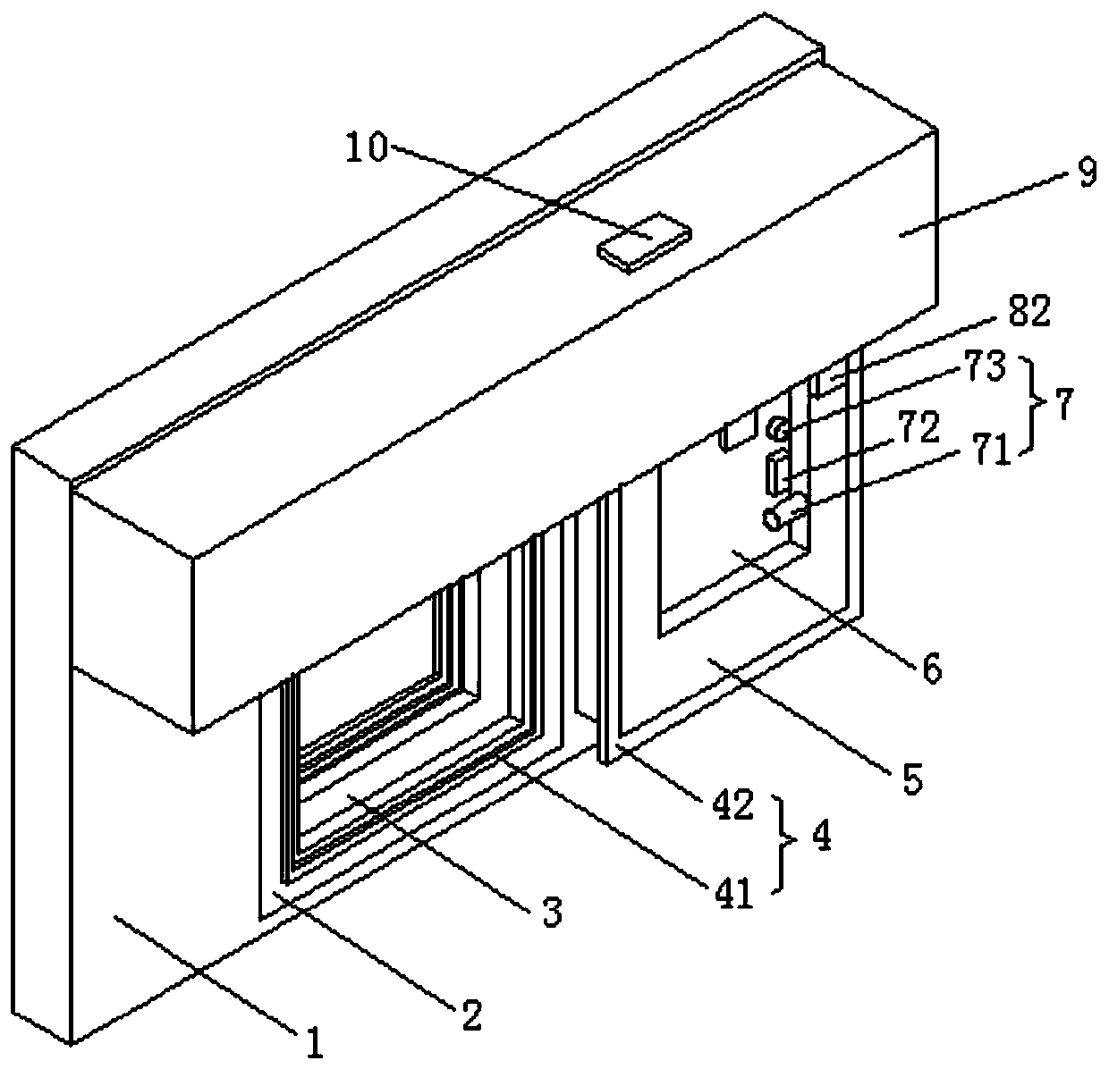
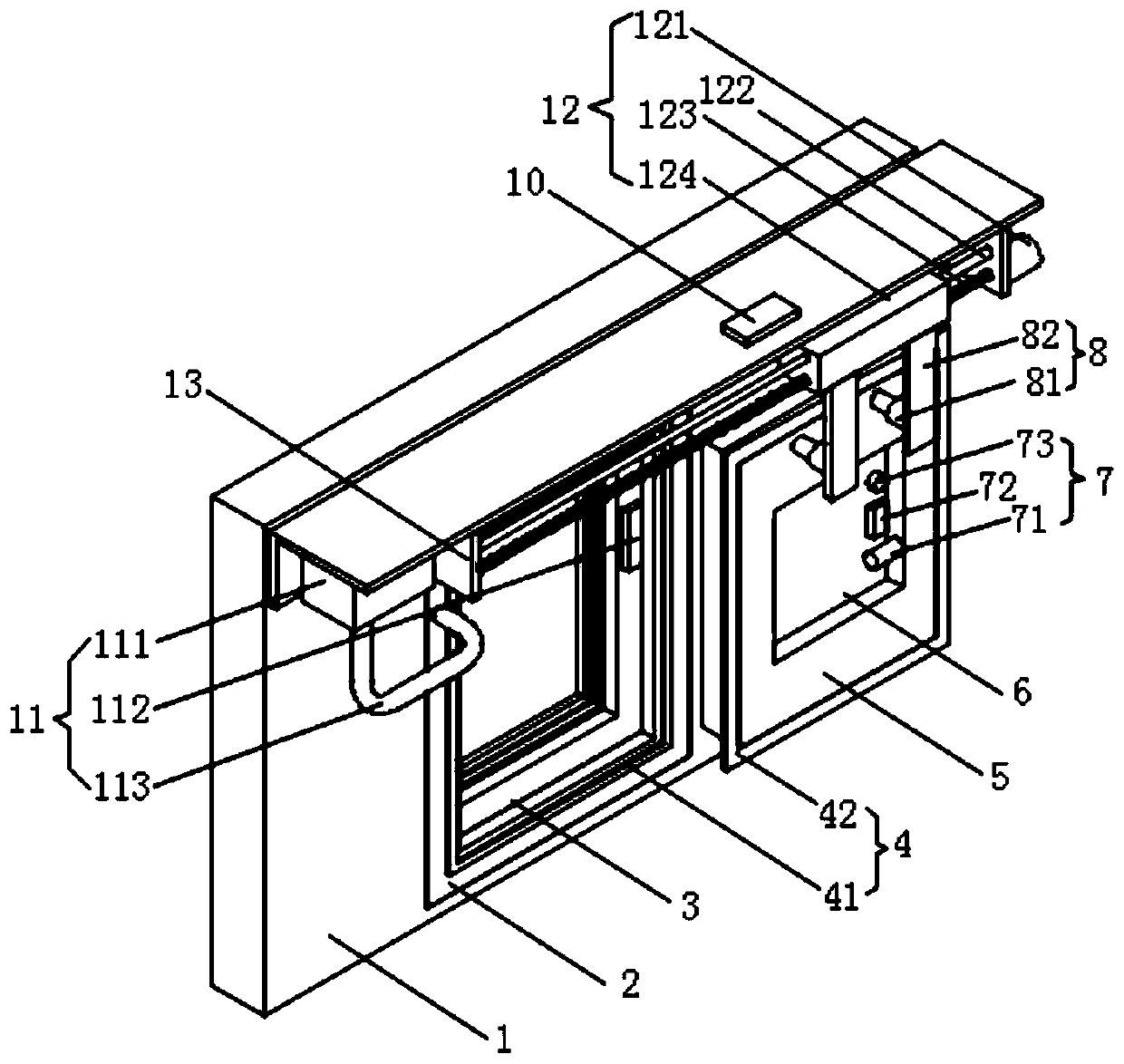
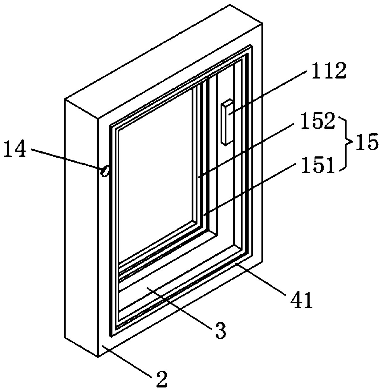
[0022] A medical airtight door, comprising a door frame 2, a mounting frame 9 and a door body 5, a door frame 2 is arranged in a through groove of the wall body 1, an annular groove 3 is opened on the inner wall of the door frame 2, and an annular groove 3 is arranged on the inner wall of the door frame 2, and the rear side of the annular groove 3 is provided on the inner wall of the door frame 2. There is an inner sealing unit 15, a through hole 14 is opened on the upper left side of the front side of the door frame 2, the mounting frame 9 is arranged on the wall 1, and is located above the door frame 2, and a detection unit 11 is provided in the mounting frame 9 and the annular groove 3 , the installation frame 9 is provided with a left-right symmetrical fixed plate 13, a reciprocating unit 12 is arranged between the two fixed plates 13, a telescopic unit 8 is provided on the reciprocating unit 12, and the door body 5 is arranged on the telescopic unit 8, and is connected with...

Embodiment 2

[0025] The difference between this embodiment and Embodiment 1 is:

[0026] In this embodiment, the outer sealing unit 4 includes an outer sealing gasket 41 and an outer sealing frame 42, the outer sealing gasket 41 is arranged on the inner wall of the door frame 2 at the front side of the annular groove 3, and the outer sealing frame 42 is arranged in front of the four sides of the door body 5. On the side, the outer gasket 41 corresponds to the outer sealing frame 42 .

[0027] Reciprocating unit 12 comprises servo motor 121, guide rod 122, screw mandrel 123 and slide block 124, is connected with screw mandrel 123 by bearing rotation between two fixed plates 13, is fixed with screw mandrel 123 parallel with screw mandrel 123 between two fixed plates 13 The guide rod 122, the screw mandrel 123 and the side of the slider 124 are threaded through screw holes, the guide rod 122 and the side of the slider 124 are slidably connected through the slide hole, and the servo motor 121 ...

Embodiment 3

[0030] The difference between this embodiment and Embodiment 1 is:

[0031] In this embodiment, the telescopic unit 8 includes an electric telescopic rod 81 and two connecting plates 82. The lower surface of the slider 124 is provided with a symmetrical connecting plate 82, and the rear side of the connecting plate 82 is provided with an electric telescopic rod 81. The end of the rod 81 is connected to the upper end of the front side of the door body 5 , and the electric telescopic rod 81 is electrically connected to the PLC controller 10 .


PUM


Abstract

The invention discloses a medical airtight door, including a door frame, a mounting frame and a door body. A through groove of a wall body is provided with the door frame, the inner wall of the door frame is provided with an annular groove, the inner wall, located on the back side of the annular groove, of the door frame is provided with an inner sealing unit, the upper end of the left side of thefront side face of the door frame is provided with a through hole, the mounting frame is arranged on the wall body, and is located on the left side below the mounting frame, a detection unit is arranged in the mounting frame and the annular groove, left and right symmetrical fixing plates are arranged in the mounting frame, a reciprocating unit is arranged between the two fixing plates, an expansion unit is arranged on the reciprocating unit, the door body is arranged on the expansion unit, and corresponds to the door frame, an outer sealing unit is arranged on the door body and the door frame, an observation window through groove is formedin the door body, and a glass window is arranged in the observation window through groove in a matched mode.According to the medical airtight door, thesealing effect can be detected, sealing performance is good, fog cannot be generated on the glass window, and use is convenient.

Description

technical field [0001] The invention relates to the technical field of medical airtight doors, in particular to a medical airtight door. Background technique [0002] Medical airtight doors are mainly to protect the cleanliness and safety of the indoor environment. Different from ordinary doors, because they need to isolate the external air and bacteria, so as to ensure that the air in the operating room is clean and sterile, they must have good sealing, and A glass window is required to facilitate the observation of the interior and ensure that the glass window will not fog up. In the existing medical purification project, the airtight door used has the problem of poor airtightness, and cannot detect whether it is sealed, and the temperature difference between indoor and outdoor is large. It is also easy to fog when it is used, so there is a need for a medical airtight door that can detect the sealing effect and has good sealing performance, and the glass window will not fo...

Claims


Application Information

Patent Timeline
Patent Type & Authority Applications(China)
IPC IPC(8): E06B5/10E06B7/16E06B7/28E06B3/46E05F15/652G01M3/26F26B21/00F26B21/06
CPCE05F15/652E05Y2900/132E06B3/4645E06B5/10E06B7/16E06B7/28F26B21/004F26B21/06G01M3/26
Inventor 曹春琳
Owner 广州海洁尔医疗设备有限公司
Why Eureka
Try Eureka