Electro-hydraulic servo biaxial pipeline fatigue test device

An electro-hydraulic servo and fatigue test technology, which is applied in the direction of measuring device, testing material hardness, testing material strength by applying repetitive force/pulsation force, etc., can solve the problems of difficult testing of the hardness of different lengths of pipes and difficult estimation of pipe data, etc. Achieve the effect of simple structure and convenient use

Active Publication Date: 2019-11-22
烟台华腾技术有限公司
View PDF15 Cites 2 Cited by
  • Summary
  • Abstract
  • Description
  • Claims
  • Application Information

AI Technical Summary

Problems solved by technology

[0004] The purpose of the present invention is to solve the problem that most of the tests carried out on the pipes on the existing automobiles when they leave the factory are tests in the uniaxial direction, which is difficult

Method used


Image

  • Electro-hydraulic servo biaxial pipeline fatigue test device
  • Electro-hydraulic servo biaxial pipeline fatigue test device
  • Electro-hydraulic servo biaxial pipeline fatigue test device

Examples


Embodiment 1

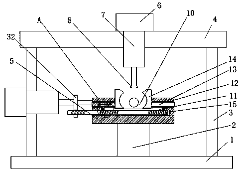
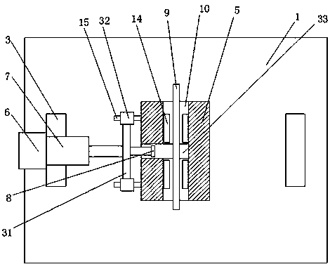
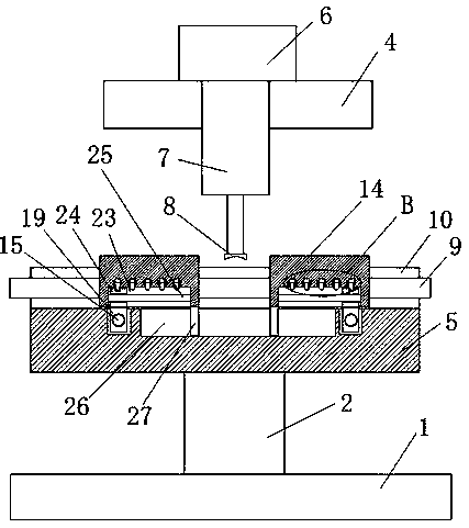
[0027] refer to Figure 1-5 , an electro-hydraulic servo biaxial pipeline fatigue test device, including a base 1, two mutually symmetrical support plates 3 are fixedly installed on the top of the base 1, the same cover plate 4 is fixedly installed on the top of the two support plates 3, and the base 1 A support seat 2 is fixedly installed on the top of the cover plate 4, and a controller 6 is fixedly installed on the top of the cover plate 4 and the support plate 3 on one side. The controller 6 is fixedly connected with a hydraulic cylinder 7, and the piston of the hydraulic cylinder 7 is fixedly installed with an arc shaped top plate 8, the top of the support seat 2 is fixedly equipped with an operation table 5, and the top of the operation table 5 is provided with a placement groove 10, and the pipe material 9 is placed in the placement groove 10, and two symmetrically arranged on the bottom inner wall of the placement groove 10. Sliding groove 11, rotating rod 15 is connec...

Embodiment 2

[0038] refer to Figure 1-5, an electro-hydraulic servo biaxial pipeline fatigue test device, including a base 1, two mutually symmetrical support plates 3 are welded on the top of the base 1, the same cover plate 4 is welded on the top of the two support plates 3, and the top of the base 1 A support seat 2 is welded, a controller 6 is welded on the top of the cover plate 4 and the support plate 3 on one side, the controller 6 is fixedly connected with a hydraulic cylinder 7, and the piston of the hydraulic cylinder 7 is welded with an arc-shaped top plate 8, supporting The top of the seat 2 is welded with an operation table 5, and the top of the operation table 5 is provided with a placement groove 10, and the pipe material 9 is placed in the placement groove 10, and two symmetrically arranged sliding grooves 11 are provided on the bottom inner wall of the placement groove 10. 11 is connected with a rotary rod 15 for rotation, and one end of the rotary rod 15 runs through the...


PUM


Abstract

The invention belongs to the field of fatigue test equipment, in particular to an electro-hydraulic servo biaxial pipeline fatigue test device. In view of the fact that most of the tests of pipe fittings on existing automobiles are the texts of single axes, the data of other aspects of the pipe fittings are difficult to estimate and the hardness of different lengths of pipe fittings is difficult to test, the following scheme is proposed. The electro-hydraulic servo biaxial pipeline fatigue test device comprises a base. Two symmetrical support plates are fixedly mounted on the top of the base.The same cover plate is fixedly mounted on the top of the two support plates. A support base is fixedly mounted on the top of the base. The top of the cover plate and the support plate on one side arefixedly provided with a controller. A hydraulic cylinder is fixedly connected on the controller. An arc top plate is fixedly mounted on the piston of the hydraulic cylinder. The device is simple in structure and convenient to use, and the whole device is enabled to perform the biaxial test on the pipe material and the hardness of the pipe material at different lengths can also be tested so as tobe convenient for people to use.

Description

technical field [0001] The invention relates to the technical field of fatigue test equipment, in particular to an electro-hydraulic servo biaxial pipeline fatigue test device. Background technique [0002] Fatigue failure is one of the most important failure forms of automotive structural parts. It is of great significance to conduct fatigue tests on specimens in the laboratory to study the fatigue characteristics and fatigue life curves of specimens. The laboratory fatigue test method and accuracy are the key to the prediction of the fatigue life of the specimen, which is conducive to preventing and solving the fatigue failure problem of the specimen under cyclic loading and improving its reliability. [0003] Most of the tests on the pipe parts on the car are uniaxial tests, which is difficult to estimate the data in other directions of the pipe, and it is difficult to test the hardness of the pipe with different lengths, so we propose an electro-hydraulic servo two-axis ...

Claims


Application Information

Patent Timeline
IPC IPC(8): G01N3/04G01N3/36G01N3/40
CPCG01N3/04G01N3/36G01N3/40G01N2203/0411G01N2203/0005G01N2203/0048G01N2203/0073G01N2203/0076
Inventor 倪宇佩李祥至
Owner 烟台华腾技术有限公司
Why Eureka
Try Eureka